
Related Manuals for SIGMATEK NC 100


Summary of Contents for SIGMATEK NC 100
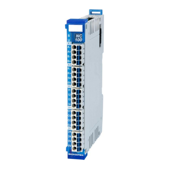
- Page 1 NC 100 S-DIAS Positioning Module Instruction Manual Date of creation: 09.09.2013 Version date: 26.07.2023 Article number: 20-011-100-E...
- Page 2 (print, photocopy, microfilm or in any other process) without the express permission. We reserve the right to make changes in the content without notice. The SIGMATEK GmbH & Co KG is not responsi- ble for technical or printing errors in the handbook and assumes no responsibility for damages that occur through...
- Page 3 4 digital outputs 1 Incremental encoder input The S-DIAS NC 100 positioning module has four digital outputs, four digital inputs, as well as an incremental encoder (optional TTL or RS422 signal). With the digital inputs, the signal statuses ("0" and "1") can be read with a +24 V reference.
-
Page 4: Table Of Contents
NC 100 S-DIAS POSITIONING MODULE Contents Introduction ................5 Target Group/Purpose of this Operating Manual ...... 5 Important Reference Documentation ......... 5 Contents of Delivery ..............5 Basic Safety Directives ............6 Symbols Used ................6 Disclaimer ..................8 General Safety Directives ............9 Software/Training ............... - Page 5 S-DIAS POSITIONING MODULE NC 100 Mechanical Dimensions ............16 Connector Layout ..............17 Status LEDs ................. 18 Applicable Connectors ............... 19 Label Field ................... 20 Wiring ..................21 Wiring Example ................21 General Information on the Digital Outputs ......22 Notes ....................
- Page 6 NC 100 S-DIAS POSITIONING MODULE 11.2 Cycle Times equal to or higher than 1 ms (in ms)....33 12 Transport/Storage ..............34 13 Storage ...................34 14 Maintenance ................35 14.1 Service ..................35 14.2 Repair ................... 35 15 Disposal ..................35 16 Hardware Class NC100 ............36 16.1...
-
Page 7: Introduction
General knowledge of automation technology is required. Further help and training information, as well as the appropriate accessories can be found on our website www.sigmatek-automation.com. Our support team is happily available to answer your questions. Please see our website for our hotline number and business hours. -
Page 8: Basic Safety Directives
NC 100 S-DIAS POSITIONING MODULE Basic Safety Directives Symbols Used The following symbols are used in the operator documentation for warning and danger messages, as well as informational notes: DANGER Danger indicates that death or serious injury will occur, if the speci- fied measures are not taken. - Page 9 S-DIAS POSITIONING MODULE NC 100 INFORMATION Information Provides important information on the product, handling or relevant sections of the documentation, which require atten- tion. 26.07.2023 Page 7...
-
Page 10: Disclaimer
It does not guarantee properties under the warranty. Please thoroughly read the corresponding documents and this operat- ing manual before handling a product. SIGMATEK GmbH & Co KG is not liable for damages caused through, non-compliance with these instructions or applicable regulations. -
Page 11: General Safety Directives
S-DIAS POSITIONING MODULE NC 100 General Safety Directives The Safety Directives in the other sections of this operating manual must be observed. These instructions are visually emphasized by symbols. INFORMATION According to EU Directives, the operating manual is a component of a product. -
Page 12: Software/Training
NC 100 S-DIAS POSITIONING MODULE CAUTION Handle the device with care and do not drop or let fall. Prevent foreign bodies and fluids from entering the device. The device must not be opened! Manipulez l’appareil avec précaution et ne le laissez pas tomber. -
Page 13: Standards And Directives
The product was constructed in compliance with the following European Union directives and tested for conformity. 3.1.1 EU Conformity Declaration EU Declaration of Conformity The product NC 100 conforms to the following European directives: • 2014/35/EU Low-voltage Directive • 2014/30/EU Electromagnetic Compatibility (EMC Directive) •... -
Page 14: Type Plate
NC 100 S-DIAS POSITIONING MODULE Type Plate HW: Hardware version SW: Software version Page 12 26.07.2023... -
Page 15: Technical Data
S-DIAS POSITIONING MODULE NC 100 Technical Data Digital Input Specification Number Input voltage typically +24 V maximum +30 V Signal level low: < +8 V high: > +14 V (up to HW version 2.10) Signal level low: < +5 V high: >... -
Page 16: Incremental Encoder Input Specifications
NC 100 S-DIAS POSITIONING MODULE Incremental Encoder Input Specifications Number of channels Input signals incremental encoder signals RS422 (A, /A, B, /B, R, /R) RS422 signal (120 termination, integrated in module) incremental encoder signal TTL (A, B, R) TTL level (1200 Pull-Up, integrated in module) -
Page 17: Environmental Conditions
S-DIAS POSITIONING MODULE NC 100 Environmental Conditions Storage temperature -20 ... +85 °C Environmental temperature 0 ... +60 °C Humidity 0-95 %, non-condensing Installation altitude above sea 0-2000 m without derating level > 2000 m up to a maximum of 5000 m with derating of the maximum environmental temperature by 0.5 °C per 100 m... -
Page 18: Mechanical Dimensions
NC 100 S-DIAS POSITIONING MODULE Mechanical Dimensions Page 16 26.07.2023... -
Page 19: Connector Layout
S-DIAS POSITIONING MODULE NC 100 Connector Layout INFORMATION The connections of the GND supply (X5: pin 3 and pin 4) are internally bridged. To supply the module, only one connection a GND pin (pin 3 or pin 4) is required. The bridged connections may be used for further looping of the GND supply. -
Page 20: Status Leds
NC 100 S-DIAS POSITIONING MODULE Status LEDs Module Status green module active no supply available BLINKING (5 Hz) no communication User yellow can be set from the application (e.g. the module LED can be set to blinking through the visualiza-... -
Page 21: Applicable Connectors
S-DIAS POSITIONING MODULE NC 100 Applicable Connectors Connectors: X1 – X5: Connectors with spring terminals (included in delivery) The spring terminals are suitable connecting ultrasonically compacted (ultrasonically weld- ed) strands. Connections: Stripping length/Sleeve length: 10 mm Plug-in direction: parallel to conductor axis or to PCB Conductor cross section, rigid: 0.2-1.5 mm... -
Page 22: Label Field
NC 100 S-DIAS POSITIONING MODULE Label Field Manufacturer Weidmüller Type MF 10/5 CABUR MC NE WS Weidmüller article number 1854510000 Compatible printer Weidmüller Type Printjet Advanced 230V Weidmüller article number 1324380000 Page 20 26.07.2023... -
Page 23: Wiring
S-DIAS POSITIONING MODULE NC 100 Wiring Wiring Example 26.07.2023 Page 21... -
Page 24: General Information On The Digital Outputs
NC 100 S-DIAS POSITIONING MODULE General Information on the Digital Outputs The cross section of the +24 V and 0 V supply must be designed for the maximum output current drawn by a group. INFORMATION When inductive loads are not equipped with a protective circuit, the high surge current flows over the 0 V line when the load is disconnect- ed since the internal protective circuit is wired against 0 V. -
Page 25: Notes
S-DIAS POSITIONING MODULE NC 100 Notes The input filters, which suppress noise signals, allow operation in harsh environmental conditions. In addition, a careful wiring method is recommended to ensure error-free func- tion. The following guidelines should be observed: • Avoid parallel connections between input lines and load-bearing circuits. -
Page 26: Assembly/Installation
NC 100 S-DIAS POSITIONING MODULE Assembly/Installation Check Contents of Delivery Ensure that the contents of the delivery are complete and intact. See chapter Contents of Delivery. INFORMATION On receipt and before initial use, check the device for damage. If the device is damaged, contact our customer service and do not install the device in your system. -
Page 27: Mounting
S-DIAS POSITIONING MODULE NC 100 Mounting The S-DIAS modules are designed for installation into the control cabinet. To mount the modules a DIN-rail is required. The DIN rail must establish a conductive connection with the back wall of the control cabinet. The individual S-DIAS modules are mounted on the DIN rail as a block and secured with latches. - Page 28 NC 100 S-DIAS POSITIONING MODULE Recommended minimum distances of the S-DIAS modules to the surrounding components or control cabinet wall: a, b, c … distances in mm (inches) Page 26 26.07.2023...
-
Page 29: Addressing
S-DIAS POSITIONING MODULE NC 100 10 Addressing 10.1 Address Mapping Overview Address Size Access Type Description (hex) (bytes) Read Cyclically Digital input register Bit 0: input 1 Bit 1: input 2 0003 Bit 2: input 3 Bit 3: input 4 Bit 7..4: reserved... - Page 30 NC 100 S-DIAS POSITIONING MODULE Input latch configuration Bit 1..0: Input 1 latches incremental encoder value 00: inactive 01: rising edge 10: falling edge 11: both edges Bit 3..2: Input 2 latches incremental encoder value 00: inactive 01: rising edge...
-
Page 31: Count Up
S-DIAS POSITIONING MODULE NC 100 Incremental encoder command register Bit 1..0: reserved Bit 2: null position input inversion (1 = inverted) Bit 3: Phase B inversion (1 = inverted) Bit 5..4: edge sampling time 001A 0 = incremental encoder disabled... -
Page 32: Count Down
NC 100 S-DIAS POSITIONING MODULE 10.3 Count Down When input B leads the input A, the counters (Period Counter Latch and Incremental En- coder Counter) decrement. 10.4 Register Period Counter The Period Counter counts between two rising edges (or between two falling edges when phase B Inversion is active) of input B. -
Page 33: Register Period Counter Level
S-DIAS POSITIONING MODULE NC 100 10.5 Register Period Counter Level The counter range is between 0 and the counter level. The up counter is used for the posi- tive direction of rotation, the down counter is used for the negative direction of rotation. -
Page 34: Register Incremental Encoder Counter
NC 100 S-DIAS POSITIONING MODULE 10.6 Register Incremental Encoder Counter Bits 5...4 of Incremental Encoder Command register sets the counter mode: 0b00 (0): the counter doesn’t count. 0b01 (1): 1-Edge mode => the counter counts on rising edge of input A only 0b10 (2): 2-Edge mode =>... -
Page 35: Supported Cycle Times
S-DIAS POSITIONING MODULE NC 100 11 Supported Cycle Times 11.1 Cycle Times below 1 ms (in µs) x= supported 11.2 Cycle Times equal to or higher than 1 ms (in ms) x= supported x= supported 26.07.2023 Page 33... -
Page 36: Transport/Storage
NC 100 S-DIAS POSITIONING MODULE 12 Transport/Storage INFORMATION This device contains sensitive electronics. During transport and stor- age, high mechanical stress must therefore be avoided. For storage and transport, the same values for humidity and vibration as for operation must be maintained! Temperature and humidity fluctuations may occur during transport. -
Page 37: Maintenance
S-DIAS POSITIONING MODULE NC 100 14 Maintenance INFORMATION During maintenance as well as servicing, observe the safety instruc- tions from chapter 2 Basic Safety Directives. 14.1 Service This product was constructed for low-maintenance operation. 14.2 Repair INFORMATION In the event of a defect/repair, send the device with a detailed error description to the address listed at the beginning of this document. -
Page 38: Hardware Class Nc100
16 Hardware Class NC100 Hardware class NC100 for the S-DIAS NC100 encoder module This hardware class is used to control the NC 100 hardware module with an incremental encoder input, four digital inputs and four digital outputs. More information on the hardware can be found in the module documentation. -
Page 39: Interfaces
S-DIAS POSITIONING MODULE NC 100 16.1 Interfaces 16.1.1 Clients The client must be connected to an S-DIAS port, an "SdiasOut"_[x]” server. SdiasIn Place The physical location of the hardware module is entered in this client. Up to 64 modules, 0 to 63, can be assigned. - Page 40 NC 100 S-DIAS POSITIONING MODULE PeriodCounterBits Here, the length of the signed period counter is defined. The entry is made in bits (default: 16). The maximum length is 32 bits. If for example, the value 16 is entered, the period counter operates with a length of 16 bits and can therefore have a value range of -32767 to +32767.
-
Page 41: Servers
S-DIAS POSITIONING MODULE NC 100 16.1.2 Servers ClassState This server shows the actual status of the hardware class. DeviceID The device ID of the hardware module is shown in this server. FPGAVersion FPGA version of the module in 16#XY (e.g. 16#10 = version 1.0). -
Page 42: Communication Interfaces
NC 100 S-DIAS POSITIONING MODULE VoltageOkEncoder Supply voltage of the incremental encoder. power supply error power supply OK PosLatchedInput[1-4], Pos- Latch position of the incremental encoder of the according latch input. LatchedZpuls (Needs FPGA version 1.5 or higher) 16.1.3 Communication Interfaces... -
Page 43: Internal Properties
S-DIAS POSITIONING MODULE NC 100 16.2 Internal Properties Influence of the Setting for “UseNewLatchConfig” 16.2.1 With the client "UseNewLatchConfig", the feature available since FPGA version 1.5 can be activated, that provides an own latch value for each input (Input 1-4, ZeroPos). -
Page 44: Influence Of The Setting For "Periodprescale
NC 100 S-DIAS POSITIONING MODULE Influence of the Setting for “PeriodPrescale” 16.2.3 The period counter for speed measurement is reset at each increment of the incremental encoder. Between two increments the period counter is increased by 1 in each cycle of the internal clock. -
Page 45: Calculation Examples For Settings Of
S-DIAS POSITIONING MODULE NC 100 16.2.4 Calculation Examples for Settings of: • PeriodPrescaler • PeriodCounterBits The value for Clock is set to 50 Mhz. The setting of "EncoderSampling" has no effect on the calculation! The server "Speed" shows the rotation speed in RPM only in integer. - Page 46 NC 100 S-DIAS POSITIONING MODULE Example 1: Calculation with default settings Clock 50 [MHz] EncCPR PeriodPrescaler PeriodCounterBits (1-32) 16 = -32768 to +32767 Time to detect stop 2,6 ms Time one period 0,08 µs min Speed 46 RPM max Speed...
-
Page 47: Cable Break At Zpuls Inputs
S-DIAS POSITIONING MODULE NC 100 Example 3: Increasing the PeriodCounterBits Clock 50 [MHz] EncCPR PeriodPrescaler PeriodCounterBits (1-32) 32 = -2147483648 to +2147483647 Time to detect stop 171798,7 ms Time one period 0,08 µs min Speed 1 RPM max Speed 1500000 RPM A prescale factor of 4 (= default) and a clock frequency of 50 MHz result in a PeriodTime of 0.08 µs. - Page 48 NC 100 S-DIAS POSITIONING MODULE Documentation Changes Change date Affected Chapter Note page(s) 10.10.2013 Changed values 24.10.2013 23.12.2013 3 Connector Layout Changed image 4.1 Wiring Example Added wiring example 11.02.2014 3 Connector Layout Changed image 3.2 Applicable Connectors Connection capacity added 01.04.2014...
- Page 49 S-DIAS POSITIONING MODULE NC 100 14.11.2019 7 Supported Cycle Times Chapter added 28.02.2020 7 Supported Cycle Times Text adapted 25.03.2020 3 Connector Layout Text corrected 08.09.2020 8 Hardware Class NC100 Chapter added 04.11.2020 5 Mounting Expansion functional ground connection 01.07.2021 1.3 Incremental Encoder...
Need help?
Do you have a question about the NC 100 and is the answer not in the manual?
Questions and answers