
Related Manuals for VERDER VERDERAIR E-PURE ATEX


Summary of Contents for VERDER VERDERAIR E-PURE ATEX
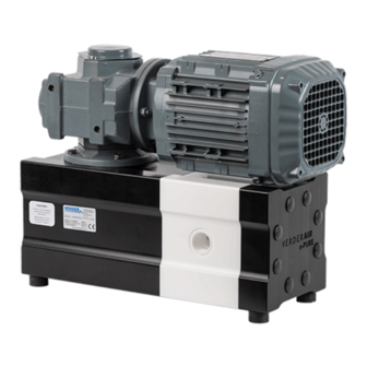
- Page 1 VERDERAIR E-PURE ATEX The most efficient electric diaphragm pumps Find you local supplier at www.verderliquids.com or scan the QR code...
-
Page 2: Table Of Contents
TABLE OF CONTENTS Pump Matrix ATEX Warnings Installation Electrical Connections Operation Maintenance / Repair Troubleshooting Parts & Kits Exploded Views Dimensions Technical Data Torque Values Drive Options Optional Equipment Customer Services & Guarantee VERDERAIR E-PURE ATEX_v1 | 30.10.2023... -
Page 3: Pump Matrix
PUMP MATRIX Before putting your pump in operation remove Use the matrix below to define the components of your pump. Make sure the wetted parts of the all packing materials after reception. Check the consignment for damage at once and make pump are compatible to the pumped liquid. -
Page 4: Atex
ATEX prevented by means of monitoring systems which For use in Atex environments, pumps in conductive are placed in the pump system. plastic and aluminum drive housing have to be WARNINGS used. All pumps made of conductive Polyethylene and aluminum (pump code VA-EPxx GA) are ATEX certified: II 3G Exh IIC T3 Gc. - Page 5 WARNING PLASTIC PARTS CLEANING SOLVENT HAZARD Use only compatible water-based solvents to clean plastic structural or pressure-containing parts. Many solvents can degrade plastic parts and cause them to fail, which could cause serious injury or property damage. See Technical Data in this and all other equipment instruction manuals.
- Page 6 WARNING EQUIPMENT MISUSE HAZARD Misuse can cause death or serious injury. Do not operate the unit when fatigued or under the influence of drugs or alcohol. Do not exceed the maximum working pressure or temperature rating of the lowest rated system component.
-
Page 7: Installation
Always use dependent and cannot be changed to reduce genuine Verder parts and accessories. Be sure all accessories are adequately sized and pressure cavitation. Viscous liquids are more difficult to rated to meet the system’s requirements. -
Page 8: Electrical Connections
ELECTRICAL CONNECTIONS NOTE: Follow the instructions in the motor manufacturer’s manual. Use the main power switch with the lockable position 0 to connect the electric motor. If you have pump with X3 option use overload protec- tion. Wire size, fuse size, and other electrical devices must comply with all local codes and regulations. Connection electric motor ATEX DOL operation (Option X3): 230/400V AC 50Hz, 220-242V/380- 420V AC 50Hz. - Page 9 Recommended installation drawing VERDERAIR E-PURE ATEX_v1 | 30.10.2023...
- Page 10 Mounting Fluid outlet line 1. A shut of valve should be installed just after the pump isolate the pump from the system for maintenance and installation. A drain valve To avoid serious injury or death from toxic fluid or should be installed to relief the pressure of the fumes: pump.
-
Page 11: Operation
OPERATION Flush the pump before first use The pump was tested before leaving the factory. 3. Place the suction tube in fluid to be pumped. Residue of the testing water can be left in the 4. Place the end of the fluid hose into an pump. -
Page 12: Maintenance / Repair
Pressure Relief Procedure Flushing Follow the pressure relief procedure whenever you The pump can be shut down with the medium see this symbol. inside. However, do not leave the pump in this This equipment stays pressurized until pressure condition for many hours without supervision - is relieved manually. - Page 13 Cleaning the pump Preventive maintenance schedule 1. Remove the hose from the suction side of the Establish a preventive maintenance schedule, pump. based on the pump’s service history. This is 2. Remove the hose from the discharge side, and especially important for prevention of spoils or attach different hoses to the suction side and the leakage due to diaphragm failure.
- Page 14 Each time the eccentric shaft is replaced, carry out a visual inspection of the other parts of the drive section, check the sliding sleeves (12) and drive shaft seal (13) for damage and signs of excessive wear. Ensure that the drive shaft (14) and guide shafts (20) are in good condition Disassembly Important:...
- Page 15 Disassembly of the drive and side housing To have access the internal parts of the pump, it must be dismantled first. Unscrew the bolts (44) on the shaft cover (43), then unscrew screw of eccentric shaft (31) and remove the spacer (30).
- Page 16 Disassembly of the drive side If the eccentric shaft with bearings and holder have Eccentric shaft moves in the ellipse (19) which is been dismantled, they must be replaced! Never bolted to the guide shafts (20) and drive shaft (14). use the same set! Unscrew the bolt (23) and take off the guide shaft Assembly...
- Page 17 Drive housing cap (39) the O-ring accordingly (46), position the drive housing cap (39), pressing it down and making sure that it adheres evenly over the entire surface to ensure dust tightness. Tighten the screws of the drive entrainment (49). Remember to tighten the screws to the correct torque (page 26).
-
Page 18: Troubleshooting
TROUBLESHOOTING Problem Cause Solution Drive will not operate - No power on the line - Check the connection of the electric plug and the general power supply - Switch on or/and set the frequency - The frequency controller is turned off controller or not set - Check all electric wires are correct... -
Page 19: Parts & Kits
PARTS & KITS Parts SEE SEPERATE PARTS LIST Kits In case of break down, we recommended to have a spare part kit for your pump on stock. ECCENTRIC SHAFT SET, CONTENT Quantity SET OF ECCENTRIC SHAFT WITH BEARINGS AND HANDLE VA-EP: Bearing holder (9) Bearing holder screws (10) Eccentric shaft (15) -
Page 20: Exploded Views
EXPLODED VIEWS VA-EPxxxA (…) POS. PART NAME QUANTITY CENTER HOUSING, VA-EP DRIVE HOUSING, VA-EP HOUSING END PLATE, VA-EP FLAPPER VALVE SUCTION, VA-EP FLAPPER VALVE DISCHARGE, VA-EP DISCHARGE VALVE PIN DISCHARGE VALVE PIN BOLT DIAPHRAGM SHAFT BEARING BEARING HOLDER BEARING HOLDER SCREWS SLIDING SLEEVE DRIVE SHAFT DRIVE SHAFT SEAL DRIVE SHAFT... -
Page 21: Dimensions
NAZWA PRODUKTU / PRODUCT NAME VA-EP (ATEX) 09.10.2023 VERDERAIR E-PURE ATEX_v1 | 30.10.2023 MATERIAŁ / MATERIAL COPYRIGHT OF THIS DRAWING IS OWNED BY "VERDER NV" COPY OR DISTRIBUTION TO THIRD PARTY IS NOT PERMITTED WITHOUT WRITTEN CONFIRMATION MASA / WEIGHT SKALA / SCALE REWIZJA / REV. - Page 22 NAZWA PRODUKTU / PRODUCT NAME in mm VA-EP100 XI) 09.10.2023 MATERIAŁ / MATERIAL COPYRIGHT OF THIS DRAWING IS OWNED BY "VERDER NV" COPY OR DISTRIBUTION TO THIRD PARTY IS NOT PERMITTED WITHOUT WRITTEN CONFIRMATION TYPE MASA / WEIGHT SKALA / SCALE REWIZJA / REV.
- Page 23 E SUCTION F DISCHARGE VERDERAIR e-PURE MOUNTING FEET DIMENSIONS MOUNTING FEET DIMENSIONS TYPE TYPE 331,50 13,05 4,65 0,98 331,50 13,05 4,29 0,98 331,50 13,05 5,91 0,98 in mm in inches VERDERAIR E-PURE ATEX_v1 | 30.10.2023...
- Page 24 PERFORMANCE CHARTS VA-EP30 75 Rpm 220 Rpm 150 Rpm 295 Rpm 365 Rpm 185 Rpm 330 Rpm 110 Rpm 260 Rpm Flow (l/min) Lineair (Rpm 75/min) VA-EP50 Lineair (Rpm 110/min) Lineair (Rpm 150/min) 75 Rpm 150 Rpm 220 Rpm 295 Rpm 365 Rpm Lineair (Rpm 185/min) 110 Rpm...
-
Page 25: Technical Data
TECHNICAL DATA ISO measurements DEVICE MODEL VA-EP30 VA-EP50 VA-EP100 Drive options Center Max. flow rate (l/min) 100. Nominal port size (in) 3/4” 3/4” 1 1/4” Weight (kg) PE Conductive PE Conductive Suctionlift (mwc) Max. operating pressure (bar) Max. operating fluid temperature (ºC) PE Conductive Min. -
Page 26: Torque Values
TORQUE VALUES Torque values in Nm Device model VA-EP30 VA-EP50 VA-EP100 Housing bolts assembly (29) Drive bolts assembly (drive option, X3, XI) Drive cap screws (49) Guide shafts assembly (20) 30,0 30,0 30,0 Drive shaft assembly (14) 30,0 30,0 30,0 Bearing holder screws assembly (10) 10,0 10,0... -
Page 27: Customer Services & Guarantee
CUSTOMER SERVICES & GUARANTEE Customer services Warranty disclaimer If you require spare parts, please contact your Verder has made an effort to illustrate and describe local distributor, providing the following details: the products accurately; however, such illustrations Pump Model and descriptions are for the sole purpose of...
Need help?
Do you have a question about the VERDERAIR E-PURE ATEX and is the answer not in the manual?
Questions and answers