VERDER VERDERAIR VA 25 Instructions-Parts List Manual
Air-operated diaphragm pumps
Hide thumbs
Also See for VERDERAIR VA 25:
- Manual (36 pages) ,
- Repair parts (35 pages) ,
- Instructions-parts list manual (34 pages)
Table of Contents
Advertisement
INSTRUCTIONS–PARTS LIST
ACETAL*, CONDUCTIVE POLYPROPYLENE*, POLYPROPYLENE, AND PVDF
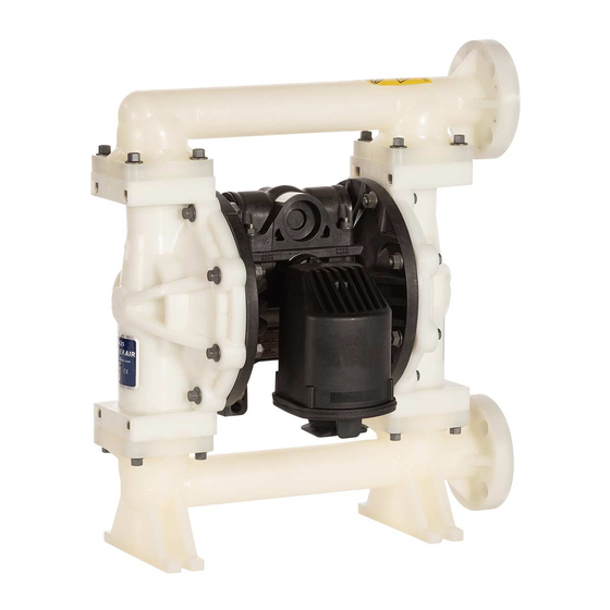
VERDERAIR VA 25
Air-Operated
Diaphragm Pumps
For fluid transfer applications. For professional use only.
8.4 bar Maximum Fluid Working Pressure
8.4 bar Maximum Air Input Pressure
This manual contains important
warnings and information.
READ AND RETAIN FOR REFERENCE
INSTRUCTIONS
*NOTE:
Refer to the Pump Listing on page 22 to
determine the Model No. of your pump.
Patent No.
CN ZL94102643.4
FR 9408894
JA 3517270
US 5,368,452
*Applies only to pumps with Acetal and
conductive polypropylene fluid sections.
*
Acetal Model Shown
819.4367
Rev. Y
EN
04155B
Advertisement
Table of Contents

Related Manuals for VERDER VERDERAIR VA 25


Summary of Contents for VERDER VERDERAIR VA 25
- Page 1 INSTRUCTIONS–PARTS LIST ACETAL*, CONDUCTIVE POLYPROPYLENE*, POLYPROPYLENE, AND PVDF VERDERAIR VA 25 Air-Operated 819.4367 Rev. Y Diaphragm Pumps For fluid transfer applications. For professional use only. 8.4 bar Maximum Fluid Working Pressure 8.4 bar Maximum Air Input Pressure This manual contains important warnings and information.
-
Page 2: Table Of Contents
D This equipment is for professional use only. D Read all instruction manuals, tags, and labels before operating the equipment. D Use the equipment only for its intended purpose. If you are not sure, call VERDER After Sales Service. D Do not alter or modify this equipment. - Page 3 Warning TOXIC FLUID HAZARD Hazardous fluid or toxic fumes can cause serious injury or death if splashed in the eyes or on the skin, inhaled, or swallowed. D Know the specific hazards of the fluid you are using. D Store hazardous fluid in an approved container. Dispose of hazardous fluid according to all local, state, and national guidelines.
-
Page 4: Installation
Contact your D Pump: Connect a ground wire and clamp as shown in VERDER Customer Service for assistance in planning a sys- Fig. 1. Loosen the grounding screw (W). Insert one end of tem to suit your needs. - Page 5 Installation Locate one bleed-type master air valve (B) close to Air Line the pump and use it to relieve trapped air. See the WARNING Warning Warning at left. Locate the other master air valve (E) upstream from all air line accessories and use it to isolate them during cleaning and repair.
- Page 6 Installation Mountings Fluid Suction Line If using a conductive (Acetal or conductive polypropy- Caution lene) pump, use conductive hoses (G). If using a non- conductive (polypropylene or PVDF) pump, ground the The pump exhaust air may contain contaminants. Ventilate fluid system. See Grounding on page 4. The pump to a remote area if the contaminants could affect your fluid fluid inlet (R) is a 1 in.
- Page 7 Installation D eight 1/2 in. flat washers Flange Connections The fluid inlet and outlet ports are 1 in. raised face flanges. D four 1/2 in. nuts. Connect 1 in. flanged plastic pipe to the pump as follows. You will need: Place a lockwasher and a flat washer on each bolt.
- Page 8 Installation Changing the Orientation of the Fluid Inlet and Fluid Pressure Relief Valve Outlet Ports Caution The pump is shipped with the fluid inlet (R) and outlet (S) ports facing the same direction. See Fig. 4. To change the Some systems may require installation of a pressure relief orientation of the inlet and/or outlet port: valve at the pump outlet to prevent overpressurization and rupture of the pump or hose.
- Page 9 Installation The air exhaust port is 3/4 npt(f). Do not restrict the air ex- Air Exhaust Ventilation haust port. Excessive exhaust restriction can cause erratic Warning pump operation. FIRE AND EXPLOSION HAZARD To provide a remote exhaust: Be sure to read FIRE OR EXPLOSION HAZARD and TOXIC FLUID HAZARD on page 3, before operating this pump.
-
Page 10: Operation
Operation Be sure the pump is properly grounded. Refer to Pressure Relief Procedure Grounding on page 4. Warning Warning Check all fittings to be sure they are tight. Be sure to use a compatible liquid thread sealant on all male threads. PRESSURIZED EQUIPMENT HAZARD Tighten the fluid inlet and outlet fittings securely. -
Page 11: Maintenance
Maintenance Lubrication Flushing and Storage Flush the pump often enough to prevent the fluid you are The air valve is designed to operate unlubricated, however if pumping from drying or freezing in the pump and damaging it. lubrication is desired, every 500 hours of operation (or month- Always flush the pump and follow the Pressure Relief Pro- ly) remove the hose from the pump air inlet and add two cedure on page 10 before storing it for any length of time. -
Page 12: Troubleshooting
Troubleshooting Relieve the pressure before checking or servicing the Warning equipment. To reduce the risk of serious injury whenever you are instructed to relieve pressure, always follow the Pressure Check all possible problems and causes before disas- Relief Procedure on page 10. sembling the pump. - Page 13 Troubleshooting PROBLEM CAUSE SOLUTION Fluid in exhaust air. Diaphragm ruptured. Replace. See pages 17–19. Loose fluid side plate (105). Tighten or replace (pages 17–19). Pump exhausts excessive air at stall. Worn air valve block (7), o-ring (6), Repair or replace. See pages 14–15. plate (8), pilot block (18), u-cups (10), or pilot pin o-rings (17).
-
Page 14: Repairing The Air Valve
Service Repairing the Air Valve Tools Required D Torque wrench D Torx (T20) screwdriver or 7 mm socket wrench †H D Needle-nose pliers D O-ring pick D Lithium base grease NOTE: Air Valve Repair Kits 819.4274 (aluminum center housing models) and 819.0249 (sst center hous- ing models) are available. - Page 15 Service Reassembly Insert narrow end first. Grease. Install with lips facing narrow end of piston (11). If you removed the bearings (12, 15), install new ones as explained on page 20. Reassemble the fluid section. Insert wide end first. On aluminum center housing models, install the valve plate seal (9†) into the groove at the bottom of the valve cavity.
-
Page 16: Ball Check Valve Repair
Service Ball Check Valve Repair Reassembly Clean all parts and inspect for wear or damage. Replace Tools Required parts as needed. D Torque wrench Reassemble in the reverse order, following all notes in Fig. 11. Assemble the ball checks exactly as shown. The arrows (A) on the fluid covers (101) must point D 10 mm socket wrench toward the outlet manifold (103). -
Page 17: Diaphragm Repair
Service Disassembly Diaphragm Repair NOTE: A Fluid Section Repair Kit is available. Refer to page 23 to order the correct kit for your pump. Parts Tools Required included in the kit are marked with an asterisk, for example (401*). Use all the parts in the kit for the best results. - Page 18 Service Unscrew one outer plate (105) from the diaphragm Reassembly shaft (24). Remove one diaphragm (401), and the inner Grease the shaft u-cup packings (402*) and install them plate (104). See Fig. 13. so the lips face out of the housing (1). See Fig. 13. Grease the length and ends of the diaphragm shaft (24), NOTE: PTFE models include a PTFE diaphragm (403) in and slide it through the housing (1).
- Page 19 Service 402* 403* 401* 04236 02637 Cutaway View, with Diaphragms in Place Cutaway View, with Diaphragms Removed 401* 403* Lips face out of housing (1). Rounded side faces diaphragm (401). Air Side must face center housing (1). Grease. Apply medium-strength (blue) Loctite or equivalent. Torque to 27 to 34 NSm at 100 rpm maximum.
-
Page 20: Bearing And Air Gasket Removal
Service Remove the air cover gaskets (22). Always replace the Bearing and Air Gasket Removal gaskets with new ones. Tools Required Use a bearing puller to remove the diaphragm shaft D Torque wrench bearings (19), air valve bearings (12) or pilot pin bear- ings (15). - Page 21 Service Insert bearings tapered end first. Press-fit bearings flush with surface of center housing (1). Apply medium-strength (blue) LoctiteR or equivalent to the threads. Torque to 14–17 NSm. 04158 Detail of Air Valve Bearings 03952B Fig. 14 819.4367...
-
Page 22: Pump Listing
Pump Listing VERDERAIR VA 25 Acetal, Polypropylene, and PVDF Pumps, Series B Your Model No. is marked on the pump’s serial plate. The listing of existing VERDERAIR VA 25 pumps is below: Fluid Part No. Section Section Seats Balls Diaphragms 810.2680... -
Page 23: Repair Kit Listing
Repair Kit Listing VERDERAIR VA 25 Acetal, Polypropylene, and PVDF Pumps, Series B Repair Kits may only be ordered as kits. To repair the air valve, order Part No. 819.4274 for aluminum center housing models and Part No. 819.0249 for stainless steel center housing models (see page 25). Parts included in the Air Valve Repair Kit are marked with a symbol in the parts list, for example (2{H). - Page 24 Notes 24 819.4367...
-
Page 25: Parts
Parts Air Motor Parts List Ref. Ref. Part No. Description Part No. Description 819.4275 HOUSING, center; alum. 10†H 819.4284 PACKING, u-cup; nitrile 819.0247 HOUSING, center; stainless 819.4285 PISTON, actuator; acetal steel 819.4286 BEARING, piston; acetal 819.4276 COVER, air valve; alum. 819.4287 BEARING, pin;... - Page 26 Fluid Section Parts List Fluid Fluid Section Section Ref. Ref. Material Material Part No. Description Part No. Description 819.4370 COVER, fluid; acetal 819.4382 COVER, fluid; PVDF 819.4371 MANIFOLD, inlet; 819.4383 MANIFOLD, inlet; acetal PVDF 819.4372 MANIFOLD, outlet; 819.4384 MANIFOLD, outlet; acetal PVDF 819.4373 PLATE, air side;...
- Page 27 Parts Seat Parts List Seat Ref. Seat Ref. Part No. Description Part No. Description Material Material 201* 819.4386 SEAT; 316 stainless 201* 819.7118 SEAT; Buna–N steel 202* NONE NOT USED – 202* 819.6344 O-RING; PTFE fluoro– 201* 819.7134 SEAT; fluoroelastomer 201* 819.4388 SEAT;...
- Page 28 Ball Parts List Diaphragm Parts List Ref. Dia- Part No. Description phragm Ref. Material Part No. Description 301* 819.4394 BALL; PTFE 401* DIAPHRAGM, not sold 301* 819.4395 BALL; acetal backup; separately polychloroprene (CR) 301* 819.4396 BALL; 316 stainless steel 402* 819.4284 PACKING, u-cup;...
- Page 29 Parts †H †H H† H† †H † †H †H *402 401* 301* 403* 201* 202* Acetal Model Shown 113* Some models use two o-rings (202), some models use four o-rings (202), and some models do not use o-rings. *301 Not used on all models. * These parts are included in the Pump Repair Kit, which may only be *201 purchased as a kit.
-
Page 30: Torque Sequence
Torque Sequence Always follow torque sequence when instructed to torque fasteners. Left/Right Fluid Covers Outlet Manifold Torque bolts to 14–17 NSm Torque bolts to 9–10 NSm Inlet Manifold Torque bolts to 9–10 NSm 30 819.4367... -
Page 31: Dimensions
Dimensions Dimensions 13.5 in. (343 mm) 7.57 in. (192 mm) 1/2 npt(f) Air Inlet 16.88 in. 12.25 in. (4.28.5 mm) (311 mm) 14.75 in. (374.5 mm) 9.8 in. (249 mm) 2.5 in. (ANSI Flange) (63.5 mm) Fluid Inlet .375 in. 3.95 in. -
Page 32: Technical Data And Performance Chart
Technical Data Maximum Fluid Working Pressure ....8.4 bar Wetted Parts ..Vary by Model. Refer to pages 25–27 Air Pressure Operating Range . -
Page 33: Customer Services/Guarantee
D Date of First Order. GUARANTEE All VERDER pumps are warranted to the original user against defects in workmanship or materials under normal use (rental use excluded) for two years after purchase date. This warranty does not cover failure of parts or components due to normal wear, damage or failure which in the judgement of VERDER arises from misuse. - Page 34 Goedgekeurd door, Approuvé par, Genehmigt von, Approvato da, Godkendt af , Έγκριζ η από, Aprovado por, Aprobado por, Hyväksynyt, Intygas av, Schválil, Kinnitanud, Jóváhagyta, Apstiprināts, Patvirtino, Zatwierdzone przez, Approvat minn, Odobril, Schválené, Одобрено от, Faofa ag, Aprobat de 15 February 2017 Werner Bosman Managing Director VERDER BV Leningradweg 5 9723 TP Groningen 819.5961 NETHERLANDS This declaration of conformity is issued under the sole responsibility of the manufacturer.
- Page 35 Goedgekeurd door, Approuvé par, Genehmigt von, Approvato da, Godkendt af , Έγκριζ η από, Aprovado por, Aprobado por, Hyväksynyt, Intygas av, Schválil, Kinnitanud, Jóváhagyta, Apstiprināts, Patvirtino, Zatwierdzone przez, Approvat minn, Odobril, Schválené, Одобрено от, Faofa ag, Aprobat de 15 February 2017 Werner Bosman Managing Director VERDER BV Leningradweg 5 9723 TP Groningen 819.5961 NETHERLANDS This declaration of conformity is issued under the sole responsibility of the manufacturer.
- Page 36 Austria Austria Belgium Belgium China China Verder Austria Verder nv Verder Shanghai Instruments and Equipment Co., Ltd Eitnergasse 21/Top 8 Kontichsesteenweg 17 Building 8 Fuhai Business Park No. 299 A-1230 Wien B–2630 Aartselaar Bisheng Road, Zhangjiang Hiteck Park AUSTRIA BELGIUM...
Need help?
Do you have a question about the VERDERAIR VA 25 and is the answer not in the manual?
Questions and answers