Table of Contents
Advertisement
Quick Links
Advertisement
Table of Contents

Subscribe to Our Youtube Channel
Related Manuals for VERDER VERDERAIR HC-PURE SB Series


Summary of Contents for VERDER VERDERAIR HC-PURE SB Series
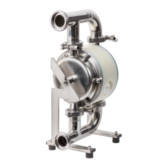
- Page 1 VERDERAIR HC-PURE SB SERIES The most efficient diaphragm pump Find you local supplier at www.verderliquids.com or scan the QR code 21-VA-MA_Manual_HC-PURE SB_rev1-en.indd 1 21-VA-MA_Manual_HC-PURE SB_rev1-en.indd 1 23-06-2023 10:13 23-06-2023 10:13...
-
Page 2: Table Of Contents
TABLE OF CONTENTS Pump matrix ATEX Warnings Installation Operation Maintenance / repair Troubleshooting Parts & kits Exploded views Dimensions Technical data Torque values Optional equipment Customer services & guarantee Notes 21-VA-MA_Manual_HC-PURE SB_rev1-en | 23.06.2023 21-VA-MA_Manual_HC-PURE SB_rev1-en.indd 2 21-VA-MA_Manual_HC-PURE SB_rev1-en.indd 2 23-06-2023 10:13 23-06-2023 10:13... -
Page 3: Pump Matrix
PUMP MATRIX Before putting your pump in operation remove Use the matrix below to define the components all packing materials after reception. Check the of your pump. Make sure the wetted parts of the consignment for damage at once and make pump are compatible to the pumped liquid. -
Page 4: Atex
ATEX WARNINGS For use in ATEX environments, pumps in conductive The following warnings are for the setup, use, materials have to be used - pumps code grounding, maintenance and repair of this VA-HCPxxXG are ATEX certified. II 2G/2GD equipment. The exclamation point symbol alerts h IIC/IIIC 70°C Gb/Gb Db. - Page 5 WARNING EQUIPMENT MISUSE HAZARD Misuse can cause death or serious injury. Do not operate the unit when fatigued or under the influence of drugs or alcohol. Do not exceed the maximum working pressure or temperature rating of the lowest rated system component.
- Page 6 WARNING PLASTIC PARTS CLEANING SOLVENT HAZARD Use only compatible water-based solvents to clean plastic structural or pressure-containing parts. Many solvents can degrade plastic parts and cause them to fail, which could cause serious injury or property damage. See Technical Data in this and all other equipment instruction manuals.
-
Page 7: Installation
INSTALLATION PLEASE CHECK THE ADDITONAL DELIVERED EXPLODED VIEW FOR ALL POSITION NUMBERS Tighten fasteners before setup Before using the pump for the first time, check and retorque the housing bolts (23). Also after the first day of operation, after periods of important temperature fluctuations, after transport, after dismantling of the pump and after periods when the pump hasn’t been working the stops, housing... - Page 8 Mounting is not placed closed to the pump, locate a bleed-type master air-valve close to the pump. Be sure the valve is easily accessible from the pump. The pump exhaust air may contain contaminants. Ventilate the remote area. MPa/bar/PSI See Air Exhaust Ventilation on page 8. Never move or lift a pump under pressure.
- Page 9 7. Inlet pressure greater than 1 bar (15 PSI), 4. The air-valves used in VA-HCP SB pumps are manufactured with tight tolerances. They should diaphragm life will be shortened. be used with clean, dry and oil-free compressed Fluid outlet line air.
-
Page 10: Operation
OPERATION Pressure Relief Procedure Pump shutdown MPa/bar/PSI MPa/bar/PSI Trapped air can cause the pump to cycle At the end of the work shift and before you check, unexpectedly, which could result in serious injury adjust, clean or repair the system, follow Pressure from splashing. -
Page 11: Maintenance / Repair
MAINTENANCE / REPAIR Flushing and storage Flush the pump often enough to prevent fluid you are pumping from drying or freezing in the pump and damage it. Always flush the pump follow the Pressure relief procedure on page 10 before storing it for any length of time. - Page 12 Figure 7a Figure 7b Figure 4 Disassembly of the center housing, diaphragms and air valve Figure 7c Figure 7d Unscrew the air inlet connector (5) and the muffler (7). Assembly Before starting to assemble please check all parts on possible damages. Especially the sealing area of the diaphragms have to be free from scratches Figure 5 Diaphragms (17) to the diaphragm shaft (19)
- Page 13 Figure 9a Figure 9b Figure 9c Figure 9d Figure 9e Figure 9f Push the air-valve housing in the center housing shaft bearing in the groove of the center housing until it touches the end cap (use the revered side of by forming them as kidney’s with locking ring pliers the AV tool for this –...
- Page 14 Adjust when necessary the position of the holes Put the gaskets (22) with the ball valves (11) on the suction manifold (3B) and with the clamps, then for the assembly pins by turning one of the diaphragms a little backwards. Screw into the put the suction manifold to the housing and tighten center housing the muffler (7) and the air inlet the clamps (24) on both connections (see figure...
-
Page 15: Troubleshooting
TROUBLESHOOTING Problem Cause Solution Pumps cycles at stall or falls to hold - Worn check valves and/or o-rings - Replace worn parts pressure at stall Pump will not cycle or cycle once and - Air valve is dirty - Clean or replace the air valve (use stops filtered air!) - Air valve is leaky... -
Page 16: Parts & Kits
PARTS & KITS Parts SEE SEPERATE PARTS LIST Kits In case of break down, we recommended to have a spare part kit for your pump on stock. SPARE PART KIT, CONTENT Quantity Gasket (22) Ball valve (11) Diaphragm (17) Shaft seal, cpl. (20) Muffler (7) Air valve cpl. -
Page 17: Exploded Views
EXPLODED VIEWS VA-HCP SB SERIES POS. PART NAME QTY. CENTER HOUSING PUMP HOUSING DISCHARGE MANIFOLD SUCTION MANIFOLD AIR INLET MUFFLER VALVE BALL DIAPHRAGM DIAPHRAGM SHAFT SCREW SHAFT SS BEARING SET SHAFT O-RING MANIFOLD INSIDE ASSEMBLY PIN SET CLAMP AIR VALVE 21-VA-MA_Manual_HC-PURE SB_rev1-en | 23.06.2023 21-VA-MA_Manual_HC-PURE SB_rev1-en.indd 17 21-VA-MA_Manual_HC-PURE SB_rev1-en.indd 17... -
Page 18: Dimensions
DIMENSIONS H - AIR INLET Dimensions in mm TYPE HCP15 DIN R¼ HCP15 TC R¼ HCP25 DIN R¼ HCP25 TC R¼ HCP40 DIN R1/2 HCP40 TC R1/2 HCP50 DIN R1/2 HCP50 TC R1/2 Dimensions in inches TYPE HCP15 DIN 8,46 6,10 R¼... - Page 19 PERFORMANCE CHARTS VA-HCP SB15 VA-HCP SB25 0,20 Nm³/min 0,30 Nm³/min 0,40 Nm³/min 0,50 Nm³/min 0,60 Nm³/min Flow rate [l/min] 21-VA-MA_Manual_HC-PURE SB_rev1-en | 23.06.2023 21-VA-MA_Manual_HC-PURE SB_rev1-en.indd 19 21-VA-MA_Manual_HC-PURE SB_rev1-en.indd 19 23-06-2023 10:13 23-06-2023 10:13...
- Page 20 PERFORMANCE CHARTS VA-HCP SB40 VA-HCP SB50 21-VA-MA_Manual_HC-PURE SB_rev1-en | 23.06.2023 21-VA-MA_Manual_HC-PURE SB_rev1-en.indd 20 21-VA-MA_Manual_HC-PURE SB_rev1-en.indd 20 23-06-2023 10:13 23-06-2023 10:13...
-
Page 21: Technical Data
TECHNICAL DATA ISO measurements Device model VA-HC15 VA-HC25 VA-HC40 VA-HC50 Nominal port size DIN 11851 DN25 DN40 DN50 DN65 Tri-clamp 1" 1,5" 2" 2,5" Air inlet BSPT R 1/4 R 1/4 R 1/2 R 1/2 Weight (kg) PE-Cond. Suction lift dry (mwc) EPDM valves PTFE valves Suction lift wet (mwc) -
Page 22: Torque Values
TORQUE VALUES Torque values for housing bolts assembly in Nm Device model VA-HCP15 SB VA-HCP25 SB VA-HCP40 SB VA-HCP50 SB Housing material PA6 Housing material PE-C Torque values for housing bolts assembly in in lb Device model VA-HCP15 SB VA-HCP25 SB VA-HCP40 SB VA-HCP50 SB Housing material PA6... -
Page 23: Customer Services & Guarantee
CUSTOMER SERVICES & GUARANTEE Customer services Warranty disclaimer If you require spare parts, please contact your Verder has made an effort to illustrate and describe local distributor, providing the following details: the products accurately; however, such illustrations Pump Model and descriptions are for the sole purpose of... -
Page 24: Notes
NOTES 21-VA-MA_Manual_HC-PURE SB_rev1-en | 23.06.2023 21-VA-MA_Manual_HC-PURE SB_rev1-en.indd 24 21-VA-MA_Manual_HC-PURE SB_rev1-en.indd 24 23-06-2023 10:13 23-06-2023 10:13...
Need help?
Do you have a question about the VERDERAIR HC-PURE SB Series and is the answer not in the manual?
Questions and answers