VERDER VERDERAIR VA 40 Instructions-Parts List Manual
Aluminium and stainless steel air-operated diaphragm pumps
Hide thumbs
Also See for VERDERAIR VA 40:
- Instructions and parts list (36 pages) ,
- Instructions manual (34 pages)
Table of Contents
Advertisement
INSTRUCTIONS–PARTS LIST
ALUMINIUM AND STAINLESS STEEL
V E R D E R AIR VA 40
Air-Operated
Diaphragm Pumps
For fluid transfer applications. For professional use only.
8.3 bar Maximum Fluid Working Pressure
8.3 bar Maximum Air Input Pressure
Important Safety Instructions
Read all warnings and instructions in the
manual. Save these instructions.
* NOTE: Refer to the Pump Listing on page 22 to
determine the Model No. of your pump.
Patent No.
CN ZL94102643.4
FR 9408894
JA 3517270
US 5,368,452
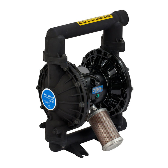
Aluminum Model Shown
819.4334
Rev. ZAC
EN
3263B
Advertisement
Table of Contents

Related Manuals for VERDER VERDERAIR VA 40


Summary of Contents for VERDER VERDERAIR VA 40
- Page 1 INSTRUCTIONS–PARTS LIST ALUMINIUM AND STAINLESS STEEL V E R D E R AIR VA 40 Air-Operated 819.4334 Rev. ZAC Diaphragm Pumps For fluid transfer applications. For professional use only. 8.3 bar Maximum Fluid Working Pressure 8.3 bar Maximum Air Input Pressure Important Safety Instructions Read all warnings and instructions in the manual.
-
Page 2: Table Of Contents
D This equipment is for professional use only. D Read all instruction manuals, tags, and labels before operating the equipment. D Use the equipment only for its intended purpose. If you are not sure, call VERDER After Sales Service. D Do not alter or modify this equipment. - Page 3 Warning TOXIC FLUID HAZARD Hazardous fluid or toxic fumes can cause serious injury or death if splashed in the eyes or on the skin, inhaled, or swallowed. D Know the specific hazards of the fluid you are using. D Store hazardous fluid in an approved container. Dispose of hazardous fluid according to all local, state, and national guidelines.
-
Page 4: Installation
The Typical Installation shown in Fig. 2 is only a guide for selecting and installing system components. Contact your VERDER Customer Service for assistance in plan- D Pump: Connect a ground wire and clamp as shown in ning a system to suit your needs. - Page 5 Installation Install a grounded, flexible air hose (A) between the Mountings accessories and the 1/2 npt(f) pump air inlet (N). See Fig. 3. Use a minimum 13 mm ID air hose. Screw an air Caution line quick disconnect coupler (D) onto the end of the air hose (A), and screw the mating fitting into the pump air The pump exhaust air may contain contaminants.
- Page 6 Installation FLOOR MOUNT TYPICAL INSTALLATION Air Supply Hose Bleed-Type Master Air Valve (required for pump) Air Regulator Air Line Quick Disconnect Master Air Valve (for accessories) Air Line Filter G Fluid Suction Hose Fluid Supply Fluid Drain Valve (required) Fluid Shutoff Valve Fluid Hose R* 1–1/2 in.
- Page 7 Installation Changing the Orientation of the Fluid Inlet and Fluid Pressure Relief Valve Outlet Ports Caution The pump is shipped with the fluid inlet (R) and outlet (S) ports facing the same direction. See Fig. 3. To change the Some systems may require installation of a pressure relief orientation of the inlet and/or outlet port: valve at the pump outlet to prevent overpressurization and rupture of the pump or hose.
- Page 8 Installation The air exhaust port is 3/4 npt(f). Do not restrict the air ex- Air Exhaust Ventilation haust port. Excessive exhaust restriction can cause erratic pump operation. Warning FIRE AND EXPLOSION HAZARD If the muffler (P) is installed directly to the air exhaust port, apply PTFE thread tape or anti–seize thread lubricant to the Be sure to read and follow the warnings and muffler threads before assembly.
-
Page 9: Operation
Operation Close the fluid drain valve (J). See Fig. 2. Pressure Relief Procedure Warning Close the pump air regulator (C). Open all bleed-type master air valves (B, E). PRESSURIZED EQUIPMENT HAZARD If the fluid hose has a dispensing device, hold it open while continuing with the following step. -
Page 10: Maintenance
Maintenance Lubrication Tightening Threaded Connections The air valve is designed to operate unlubricated, however if Before each use, check all hoses for wear or damage, and lubrication is desired, every 500 hours of operation (or replace as necessary. Check to be sure all threaded connec- monthly) remove the hose from the pump air inlet and add tions are tight and leak-free. - Page 11 Notes 819.4334...
-
Page 12: Troubleshooting
Troubleshooting Relieve the pressure before checking or servicing the Warning equipment. To reduce the risk of serious injury whenever you are instructed to relieve pressure, always follow the Pressure Check all possible problems and causes before Relief Procedure on page 9. disassembling the pump. - Page 13 Troubleshooting PROBLEM CAUSE SOLUTION Fluid in exhaust air. Diaphragm ruptured. Replace. See pages 17–19. Loose diaphragm shaft bolt (107). Tighten or replace. See pages 17–19. Damaged o-ring (108). Replace. See pages 17–19. Pump exhausts excessive air at stall. Worn air valve block (7{H), o-ring (6{H), Repair or replace.
-
Page 14: Service
Service Repairing the Air Valve Tools Required † D Torque wrench D Torx (T20) screwdriver or 7 mm socket wrench D Needle-nose pliers D O-ring pick D Lithium base grease NOTE: Air Valve Repair Kits 819.4274 (aluminum center housing models) and 819.0249 (sst center housing models) are available. - Page 15 Service Reassembly Insert narrow end first. Grease. Install with lips facing If you removed the bearings (12, 15), install new ones as narrow end of piston (11). explained on page 20. Reassemble the fluid section. Insert wide end first. On aluminum center housing models, install the valve plate seal (9†) into the groove at the bottom of the valve cavity.
-
Page 16: Ball Check Valve Repair
Service Ball Check Valve Repair Torque to 14–17 NSm. See Torque Sequence, page 28. Arrow (A) must point toward outlet manifold (103). Tools Required Not used on some models. D Torque wrench Beveled seating surface must face ball (301). D 13 mm socket wrench D O-ring pick Disassembly NOTE: A Fluid Section Repair Kit is available. -
Page 17: Diaphragm Repair
Service Diaphragm Repair Disassembly NOTE: A Fluid Section Repair Kit is available. Refer to page 23 to order the correct kit for your pump. Parts Tools Required included in the kit are marked with an asterisk, for example (401*). Use all the parts in the kit for the best results. - Page 18 Service Loosen but do not remove the diaphragm shaft Install the fluid side diaphragm plate (105) on the bolts (107), using a 15 mm socket wrench (1 in. on stain- bolt so the rounded side faces in, toward the dia- less steel models) on both bolts.
- Page 19 Service 402* 403* 401* 03274 03275 Cutaway View, with Diaphragms in Place Cutaway View, with Diaphragms Removed 401* 403* 108* Lips face out of housing (1). Rounded side faces diaphragm (401). Air Side must face center housing (1). Grease. Apply medium-strength LoctiteR or equivalent. Torque to 27–34 NSm at 100 rpm maximum.
-
Page 20: Bearing And Air Gasket Removal
Service The bearings (12, 15, and 19) are tapered and can only Bearing and Air Gasket Removal be installed one way. Insert the bearings into the center Tools Required housing (1), tapered end first. Using a press or a block and rubber mallet, press-fit the bearing so it is flush with D Torque wrench the surface of the center housing. - Page 21 Service Insert bearings tapered end first. Press-fit bearings flush with surface of center housing (1). Torque to 15–17 NSm. Detail of Air Valve Bearings 03277 03278B Fig. 13 819.4334...
-
Page 22: Pump Listing
Pump Listing VERDERAIR VA 40 Aluminium and Stainless Steel pumps, Series B Your Model No. is marked on the pump’s serial plate. The listing of existing VERDERAIR VA 40 pumps is below: Fluid Part No. Section Section Seats Balls Diaphragms Á... -
Page 23: Repair Kit Listing
Repair Kit Listing VERDERAIR VA 40 Aluminium and Stainless Steel Pumps, Series B Repair Kits may only be ordered as kits. To repair the air valve, order Part No. 819.4274 for aluminum center housing models and Part No. 819.0249 for stainless steel center housing models (see page 24). Parts included in the Air Valve Repair Kit are marked with a symbol in the parts list, for example (4{H). -
Page 24: Parts
Parts Air Motor Parts List Fluid Section Parts List Fluid Ref. Section Ref. Part No. Description Material Part No. Description 819.0226 COVER, fluid; 819.4275 HOUSING, center; alum. aluminum 819.0247 HOUSING, center; stainless 819.6980 MANIFOLD, inlet; steel aluminum 819.4276 COVER, air valve; alum. 819.4339 MANIFOLD, inlet;... - Page 25 Parts Drawing † †10 6† †17 7† †18 9† 17† 110Y 10† 301* 402* 201* 202* Aluminum Model Shown 401* 108* 403* Not used on some models. Used on PTFE models only. *301 *201 * These parts are included in the Pump Repair Kit, which may only be purchased as a kit.
- Page 26 Parts Seat Parts List 201* 819.4355 SEAT; polypropylene Seat Ref. Part No. Description Material 201* 819.4349 SEAT; 316 stainless steel 202* 819.4350 O-RING; PTFE 202* 819.4350 O-RING; PTFE 201* 819.4351 SEAT; 17-4 stainless 201* 819.4356 SEAT; PVDF steel – 202* 819.4350 O-RING;...
- Page 27 Parts Diaphragm Parts List Dia- phragm Ref. Material Part No. Description 401* not sold DIAPHRAGM, separately backup; polychloroprene (CR) 402* 819.4284 PACKING, u-cup; nitrile 401* not sold DIAPHRAGM, separately Overmolded 402* 819.4284 PACKING, u-cup; nitrile 403* 819.0270 DIAPHRAGM; PTFE 401* 819.4363 DIAPHRAGM;...
-
Page 28: Torque Sequence
Torque Sequence Always follow torque sequence when instructed to torque fasteners. Left/Right Fluid Covers Torque bolts to 22–25 NSm. SIDE VIEW Inlet Manifold Torque bolts to 14–17 NSm. BOTTOM VIEW Outlet Manifold Torque bolts to 14–17 NSm. TOP VIEW 28 819.4334... -
Page 29: Dimensions
Dimensions FRONT VIEW SIDE VIEW 197 mm Port Diameter: 132.5 mm 44.5 mm 1/2 npt(f) Air Inlet 3/4 npt(f) Air Exhaust 268 mm 45° 38 mm 152.5 mm 152.5 mm 11.5 mm 379.5 mm 265.5 mm 7438B PUMP MOUNTING HOLE PATTERN 152.5 mm Four 16 mm diameter holes... -
Page 30: Technical Data And Performance Chart
Technical Data {Fluid Inlet Size. Maximum Fluid Working Pressure ....8.4 bar ......1–1/2 in. - Page 31 Notes 819.4334...
-
Page 32: Customer Services/Guarantee
GUARANTEE All VERDER pumps are warranted to the original user against defects in workmanship or materials under normal use (rental use excluded) for two years after purchase date. This warranty does not cover failure of parts or components due to normal wear, damage or failure which in the judgement of VERDER arises from misuse. - Page 33 ATITIKTIES DEKLARACIJA, DEKLARACJA ZGODNOŚCI UE, DIKJARAZZJONI-KE TA’ KONFORMITA`, IZJAVA ES O SKLADNOSTI, ES - VYHLÁSENIE O ZHODE, ЕО-ДЕКЛАРАЦИЯ ЗА СЪВМЕСТИМОСТ, DEIMHNIÚ COMHRÉIREACHTA CE, CE-DECLARAŢIE DE CONFORMITATE Model VERDERAIR VA 40 Modèle, Modell, Modello, Μοντέλο, Modelo, Malli, Mudel, Modelis, Mudell, Модел, Samhail Part 810.0092–810.0096, 810.0101–810.0103, 810.0195–810.0198,...
- Page 34 Fax: +27 11 704 7515 e–mail: info@verder.co.za United States of America Verder Inc. 110 Gateway Drive Macon, GA 31210 Toll Free: 1 877 7 VERDER Tel: +1 478 471 7327 Fax: +1 478 476 9867 e–mail: info@verder.com 34 819.4334...
Need help?
Do you have a question about the VERDERAIR VA 40 and is the answer not in the manual?
Questions and answers