Table of Contents
Advertisement
Quick Links
INSTRUCTIONS–PARTS LIST
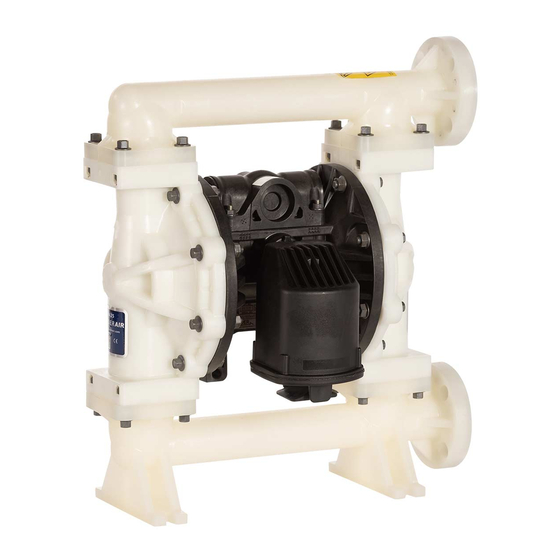
Air-Operated
Diaphragm Pumps
Intended for use in accordance with the United States Flammable and Combustible Liquids
Code (NFPA 30) and the Automotive and Marine Service Station Code (NFPA 30A).
For professional use only.
VERDER
Evacuation and Transfer Pumps
120 psi; 0.84 MPa; 8.4 bar Maximum Fluid Working Pressure
120 psi; 0.84 MPa; 8.4 bar Maximum Air Input Pressure
Part No. 810.0780*
with TPE diaphragms and seats, acetal balls
Part No. 810.0930*
with TF diaphragms and balls, fluoroelastomer seats
Patent No.
CN ZL94102643.4
FR 9408894
JA 3517270
US 5,368,452
Important Safety Instructions
Read all warnings and instructions in this manual.
Save these instructions.
This symbol on the nameplate means the
product is listed by Underwriters
Laboratories Inc. (UL Standard No. 79,
Standard for Power-Operated Pumps for
Petroleum Product Dispensing Systems).
*
II 2 GD
Ex h IIC 66°C...135°C Gb
Ex h IIIC T135°C Db
ATEX T-code rating is dependent on the temperature of the fluid
being pumped. Fluid temperature is limited by the materials of the
pump interior wetted parts. See Technical Data for the maximum
fluid operating temperature for your specific pump model.
VA 25
Model 810.0780
819.0254
Rev. L
EN
Advertisement
Table of Contents

Related Manuals for VERDER AIR VA 25


Summary of Contents for VERDER AIR VA 25
- Page 1 Intended for use in accordance with the United States Flammable and Combustible Liquids Code (NFPA 30) and the Automotive and Marine Service Station Code (NFPA 30A). For professional use only. VERDER VA 25 Evacuation and Transfer Pumps 120 psi; 0.84 MPa; 8.4 bar Maximum Fluid Working Pressure 120 psi;...
-
Page 2: Table Of Contents
Table of Contents Maintenance ........13 Symbols . -
Page 3: Symbols
This equipment is for professional use only. • Read all instruction manuals, tags, and labels before operating the equipment. • Use the equipment only for its intended purpose. If you are not sure, call your VERDER distributor. • Do not alter or modify this equipment. - Page 4 WARNING TOXIC FLUID HAZARD Hazardous fluid or toxic fumes can cause serious injury or death if splashed in the eyes or on the skin, inhaled, or swallowed. • Know the specific hazards of the fluid you are using. • Store hazardous fluid in an approved container. Dispose of hazardous fluid according to all local, state and national guidelines.
-
Page 5: Installation
Use only metal components. Contact your VERDER distributor for pails, which are conductive. Do not place the pail on assistance in planning a system to suit your needs. -
Page 6: Mountings
Installation Mountings Air Line CAUTION WARNING The pump exhaust air may contain contaminants. A bleed-type master air valve (B) is required in your Ventilate to a remote area if the contaminants could system to relieve air trapped between this valve and the affect your fluid supply. -
Page 7: Waste Oil Receiver Evacuation System, Or General Fluid Transfer Application
Installation Waste Oil Receiver Evacuation System, or General Fluid Transfer Application KEY FOR FIG. 2 Air supply line Bleed-type master air valve (required for pump) Air regulator Air line quick disconnect Master air valve (for accessories) Air line filter Fluid suction line Fluid line quick disconnect Fluid drain valve (required) Fluid shutoff valve... -
Page 8: Fuel Dispense System
Installation Fuel Dispense System KEY FOR FIG. 4 Air supply line Bleed-type master air valve (required for pump) Air regulator Air line quick disconnect Master air valve (for accessories) Air line filter Fluid suction line Fluid drain valve (required) Fluid shutoff valve Fluid line Hose reel Fuel dispense valve... -
Page 9: Air Exhaust Ventilation
Installation Air Exhaust Ventilation To provide a remote exhaust: WARNING 1. Remove the muffler (U) from the pump air exhaust port. Be sure to read and follow the TOXIC FLUID HAZARD and FIRE AND EXPLOSION HAZARD warnings on 2. Install a grounded air exhaust hose (W) and connect page 4 before operating this pump. -
Page 10: Fluid Pressure Relief Kit (For Pump Model 810.0780 Only)
Installation Fluid Pressure Relief Kit (for Pump Model 810.0780 only) Caution Pressure Relief Kit 819.6479 (Z) is available, to Thermal expansion of fluid in the outlet line can cause prevent overpressurization and rupture of the pump or overpressurization. This can occur when using long hose. -
Page 11: Operation
Operation Pressure Relief Procedure Flush the Pump Before First Use The pump was tested in water. If water could contaminate the fluid you are pumping, flush it thoroughly with a WARNING compatible solvent. Follow the steps under Starting and Adjusting the Pump on page 12. PRESSURIZED EQUIPMENT HAZARD The equipment stays pressurized until pressure is manually relieved. -
Page 12: Starting And Adjusting The Pump
Operation Starting and Adjusting the Pump Gear Oil Evacuation Systems (see Fig. 3) 1. Close the pump air regulator (C) and all bleed-type All Systems master air valves (B, E). 2. Attach an appropriate wand (S) to the suction hose WARNING (P). -
Page 13: Maintenance
Maintenance Lubrication Flushing and Storage The air valve is designed to operate unlubricated. If WARNING lubrication is desired, every 500 hours of operation (or monthly), remove the hose from the pump air inlet and add To reduce the risk of serious injury whenever you are two drops of machine oil to the air inlet. -
Page 14: Troubleshooting
Troubleshooting Relieve the pressure before checking or servicing the WARNING equipment. To reduce the risk of serious injury whenever you are Check all possible problems and causes before instructed to relieve pressure, always follow the disassembling the pump. Pressure Relief Procedure on page 11. PROBLEM CAUSE SOLUTION... -
Page 15: Service
Service Repairing the Air Valve Tools Required Torque to 50–60 in-lb (5.6–6.8 N•m). • Torque wrench • Torx (T20) screwdriver or 7 mm socket wrench • Needle-nose pliers • O-ring pick • Lithium base grease NOTE: Air Valve Repair Kit 819.4274 is available. Refer to page 24. - Page 16 Service Insert narrow end first. Grease. Install with lips facing narrow end of piston (30). Insert wide end first. Fig. 9 Fig. 10 Reassembly 1. If you replaced the bearings (28, 31), reinstall as grooves on the ends of the push pins (26). See Fig. 8. explained on page 21.
-
Page 17: Ball Check Valve Repair
Service Ball Check Valve Repair Reassembly 1. Clean all parts and inspect for wear or damage. Tools Required Replace parts as needed. • Torque wrench 2. Reassemble in the reverse order, following all notes in • 10 mm socket wrench Fig. -
Page 18: Diaphragm Repair
Service Diaphragm Repair NOTE: A Fluid Section Repair Kit is available. Refer to page 24 to order the correct kit for your pump. Parts Tools Required included in the kit are marked with an asterisk, for example (29*). Use all the parts in the kit for the best •... - Page 19 Service 4. Loosen but do not remove the diaphragm shaft bolts c. Install the diaphragm (29*) on the bolt. Make (21), using a 15 mm socket wrench on both bolts. certain the side marked AIR SIDE faces the center housing (5). 5.
- Page 20 Service Cutaway View, with Diaphragms Removed Cutaway View, with Diaphragms in Place Lips face out of housing (5). Rounded side faces diaphragm (29). Air side must face center housing (5). Grease. Apply medium-strength (blue) Loctite or equivalent. Torque to 20 to 25 ft-lb (27 to 34 N•m). Fig.
-
Page 21: Bearing And Air Gasket Removal
Service Bearing and Air Gasket Removal 8. If you removed the diaphragm shaft bearings (23), reach into the center housing (5) with an o-ring pick Tools Required and hook the u-cup packings (22), then pull them out of the housing. Inspect the packings. See Fig. 12. •... - Page 22 Service Insert bearings tapered end first. Press-fit bearings flush with surface of center housing (5). Apply medium-strength (blue) Loctite or equivalent. Torque to 120 to 150 in-lb (14 to 17 N•m). Detail of Air Valve Bearings Fig. 13 819.0254...
-
Page 23: Parts Drawing
Parts Drawing EVACUATION AND TRANSFER PUMPS Part No. 810.0780 with TPE Diaphragms and Seats, Acetal Balls Part No. 810.0930 with TF Diaphragms and Balls, Fluoroelastomer Seats Arrow (A) must point toward outlet manifold (1). †10 †22 †27 12† 13† †9 15†... -
Page 24: Parts List
819.4482 BOLT, hex hd; M12 x 1.75; 35 mm (1.38 in.) long Repair Kits Use Only Genuine VERDER Parts and Accessories Fluid Section Repair Kit 819.0986 Air Valve Repair Kit 819.4274 For Models 810.0780 and 810.0781 VA 25 pumps. For all VA 25 pumps. Includes: TPE diaphragms and seats, acetal balls. -
Page 25: Torque Sequence
Torque Sequence When instructed to torque fasteners, always follow the torque sequence. 1. Left/Right Fluid Covers 3. Outlet Manifold Torque bolts to 120–150 in–lb (14–17 N•m) Torque bolts to 120–150 in–lb (14–17 N•m) TOP VIEW SIDE VIEW 2. Inlet Manifold Torque bolts to 120–150 in–lb (14–17 N•m) BOTTOM VIEW 819.0254... -
Page 26: Technical Data
Technical Data Evacuation and Transfer Pumps (Model 810.0780) Air inlet size....... . . 1/2 npt(f) Maximum fluid working pressure . -
Page 27: Customer Services/Guarantee
All VERDER pumps are warranted to the original user against defects in workmanship or materials under normal use (rental use excluded) for two years after purchase date. This warranty does not cover failure of parts or components due to normal wear, damage or failure which in the judgement of VERDER arises from misuse. - Page 28 é 819.0254...
Need help?
Do you have a question about the AIR VA 25 and is the answer not in the manual?
Questions and answers