VERDER VERDERAIR VA 40 Instructions Manual
Hide thumbs
Also See for VERDERAIR VA 40:
- Instructions-parts list manual (34 pages) ,
- Instructions and parts list (36 pages)
Table of Contents
Advertisement
Quick Links
INSTRUCTIONS–PARTS LIST
Parts
INSTRUCTIONS
POLYPROPYLENE AND KYNARR
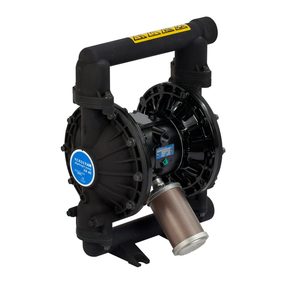
V E R D E R AIR VA 40 Air-Operated
Diaphragm Pumps
8.3 bar Maximum Fluid Working Pressure
8.3 bar Maximum Air Input Pressure
*NOTE: Refer to the Pump Listing on page 24 to determine
the Model No. of your pump.
Patents Pending
This manual contains important
warnings and information.
READ AND RETAIN FOR REFERENCE
819.4486
Rev. L
04700B
Advertisement
Table of Contents

Related Manuals for VERDER VERDERAIR VA 40


Summary of Contents for VERDER VERDERAIR VA 40
- Page 1 INSTRUCTIONS–PARTS LIST Parts This manual contains important 819.4486 warnings and information. READ AND RETAIN FOR REFERENCE INSTRUCTIONS Rev. L POLYPROPYLENE AND KYNARR V E R D E R AIR VA 40 Air-Operated Diaphragm Pumps 8.3 bar Maximum Fluid Working Pressure 8.3 bar Maximum Air Input Pressure *NOTE: Refer to the Pump Listing on page 24 to determine the Model No.
-
Page 2: Table Of Contents
D This equipment is for professional use only. D Read all instruction manuals, tags, and labels before operating the equipment. D Use the equipment only for its intended purpose. If you are not sure, call VERDER After Sales Service. D Do not alter or modify this equipment. - Page 3 Warning TOXIC FLUID HAZARD Hazardous fluid or toxic fumes can cause serious injury or death if splashed in the eyes or on the skin, inhaled, or swallowed. D Know the specific hazards of the fluid you are using. D Store hazardous fluid in an approved container. Dispose of hazardous fluid according to all local, state, and national guidelines.
-
Page 4: Installation
Hazardous fluid or toxic fumes can cause containers or piping. Contact your VERDER Customer Ser- serious injury or death if splashed in the eyes vice for assistance in grounding your system. Never use a or on the skin, inhaled, or swallowed. - Page 5 Installation D All solvent pails used when flushing, according to local Grounding (continued) code. Use only metal pails, which are conductive. Do not place the pail on a non-conductive surface, such as paper To reduce the risk of static sparking, ground the pump and all or cardboard, which interrupts the grounding continuity.
- Page 6 Installation Air Line Locate one bleed-type master air valve (B) close to the pump and use it to relieve trapped air. See the Warning Warning at left. Locate the other master air valve (E) upstream from all air line accessories and use it to isolate them during cleaning and repair.
- Page 7 Installation Mountings If the fluid inlet pressure to the pump is more than 25% of the outlet working pressure, the ball check valves will not close fast enough, resulting in inefficient pump operation. Caution At inlet fluid pressures greater than 1.05 bar, diaphragm The pump exhaust air may contain contaminants.
- Page 8 Installation Flange Connections Place a flat washer (E) on each bolt (C). Refer to Fig. 3. The fluid inlet and outlet ports are 1–1/2” raised face, stan- dard 150 lb class pipe flanges. Connect 1–1/2” flanged plas- Align the holes in the gasket (B) and the pipe flange (A) tic pipe to the pump as follows.
- Page 9 1/2 npt(f) Air Inlet Port 102 Fluid Inlet Manifold Overpressurization can also occur if the VERDERAIR VA 40 Muffler; Air Exhaust Port 103 Fluid Outlet Manifold pump is being used to feed fluid to a piston pump, and the...
- Page 10 Installation The air exhaust port is 3/4 npt(f). Do not restrict the air ex- Air Exhaust Ventilation haust port. Excessive exhaust restriction can cause erratic Warning pump operation. FIRE AND EXPLOSION HAZARD To provide a remote exhaust: Be sure to read and follow the warnings and precautions regarding TOXIC FLUID HAZARD, and FIRE OR EXPLOSION Remove the muffler (P) from the pump air exhaust port.
-
Page 11: Operation
Operation Pressure Relief Procedure Be sure the pump is properly grounded. Refer to Grounding on page 4. Warning Check all fittings to be sure they are tight. Be sure to use a compatible liquid thread sealant on all male threads. PRESSURIZED EQUIPMENT HAZARD Tighten the fluid inlet and outlet fittings securely. -
Page 12: Maintenance
Maintenance Lubrication Tightening Threaded Connections The air valve is designed to operate unlubricated. However, if Before each use, check all hoses for wear or damage, and lubrication is desired, every 500 hours of operation (or month- replace as necessary. Check to be sure all threaded connec- ly) remove the hose from the pump air inlet and add two tions are tight and leak-free. - Page 13 Notes 819.4486...
-
Page 14: Troubleshooting
Troubleshooting Relieve the pressure before checking or servicing the Warning equipment. To reduce the risk of serious injury whenever you are instructed to relieve pressure, always follow the Pressure Check all possible problems and causes before disas- Relief Procedure on page 11. sembling the pump. - Page 15 Troubleshooting PROBLEM CAUSE SOLUTION Fluid in exhaust air. Diaphragm ruptured. Replace. See pages 19–21. Loose fluid side diaphragm plate (105). Tighten or replace. See pages 19–21. Pump exhausts excessive air at stall. Worn air valve block (7), o-ring (6), Inspect; replace. See pages 16–17. plate (8), pilot block (18), u-cups (10), or pilot pin o-rings (17).
-
Page 16: Repairing The Air Valve
Service Repairing the Air Valve Tools Required D Torque wrench D Torx (T20) screwdriver or 7 mm socket wrench D Needle-nose pliers D O-ring pick D Lithium base grease NOTE: Air Valve Repair Kit 819.4274 is available. Refer to page 27. Parts included in the kit are marked with a symbol, for example (4{). - Page 17 Service Install with lips facing Reassembly narrow end of piston (11). Insert narrow end first. If you removed the bearings (12, 15), install new ones as Grease. Insert wide end first. explained on page 22. Reassemble the fluid section. Install the valve plate seal (9{) into the groove at the bottom of the valve cavity.
-
Page 18: Ball Check Valve Repair
Service Ball Check Valve Repair Torque to 9–10 N.m. Tools Required Arrow (A) must point toward outlet manifold (103). D Torque wrench Not used on some models. D 10 mm socket wrench D O-ring pick Disassembly NOTE: A Fluid Section Repair Kit is available. Refer to page 25 to order the correct kit for your pump. -
Page 19: Diaphragm Repair
Service Diaphragm Repair Warning Tools Required To reduce the risk of serious injury whenever you are D Torque wrench instructed to relieve pressure, always follow the Pressure Relief Procedure on page 11. D 13 mm socket wrench D Adjustable wrench D 19 mm socket wrench Relieve the pressure. - Page 20 Service Unscrew one outer plate (105) from the diaphragm Reassembly shaft (24). Remove one diaphragm (401), and the inner Grease the shaft u-cup packings (402*) and install them plate (104). See Fig. 13. so the lips face out of the housing (1). See Fig. 13. Grease the length and ends of the diaphragm shaft (24) NOTE: PTFE models include a PTFE diaphragm (403) in and slide it through the housing (1).
- Page 21 Service 402* 403* 401* 04708 03275 Cutaway View, with Diaphragms in Place Cutaway View, with Diaphragms Removed 401* 403* Lips face out of housing (1). Air Side must face center housing (1). Grease. Used on Models with PTFE diaphragms only. Apply medium-strength (blue) LoctiteR or equivalent.
-
Page 22: Bearing And Air Gasket Removal
Service Bearing and Air Gasket Removal Remove the air cover gaskets (22). Always replace the gaskets with new ones. Tools Required D Torque wrench Use a bearing puller to remove the diaphragm shaft bearings (19), air valve bearings (12) or pilot pin bear- D 10 mm socket wrench ings (15). - Page 23 Service Insert bearings tapered end first. Press-fit bearings flush with surface of center housing (1). Torque to 15–17 N.m. Detail of Air Valve Bearings 03277 03278B Fig. 14 819.4486...
-
Page 24: Pump Listing
Pump Listing VERDERAIR VA 40 Polypropylene and Kynar Pumps, Series B Your Model No. is marked on the pump’s serial plate. The listing of existing VERDERAIR VA 40 pumps is below: Á Á Á Á Á Á Á Á Á Á... -
Page 25: Repair Kit Listing
Repair Kit Listing VERDERAIR VA 40 Polypropylene and Kynar Pumps, Series B Repair Kits may only be ordered as kits. To repair the air valve, order Part No. 819.4274 (see page 27). Parts included in the Air Valve Repair Kit are marked with a symbol in the parts list, for example (4{). The list of existing Repair Kits is below: Á... -
Page 26: Parts
Parts Air Motor Parts List Fluid Section Parts List Fluid section Ref. Ref. Part No. Description material Part No. Description 819.4275 HOUSING, center; alum. 819.4487 COVER, fluid; polypropylene 819.7102 HOUSING, center; stainless steel 819.6981 MANIFOLD, inlet; 819.4276 COVER, air valve; alum. polypropylene 819.7103 COVER, air valve;... - Page 27 Parts 401* *402 301* 403* 201* 202* *301 *201 202* Not used on some models. * These parts are included in the Pump Repair Kit, which may only be purchased as a kit. Refer to the Repair Kit Listing on page 25 to determine the correct kit for your pump.
- Page 28 Parts Seat Parts List 201* 819.7116 SEAT; Buna–N Seat Ref. 202* NONE NOT USED Part No. Description Material – 201* 819.4349 SEAT; 316 stainless steel 201* 819.7114 SEAT; Viton 202* None Not Used 202* 819.4350 O-RING; PTFE 201* 819.4355 SEAT; polypropylene 201* 819.4351 SEAT;...
- Page 29 Parts Ball Parts List 401* 819.4363 DIAPHRAGM; Hytrel 402* 819.4284 PACKING, u-cup; nitrile Ref. Part No. Description 301* 819.4357 BALL; PTFE 401* 819.4365 DIAPHRAGM; Santoprene 301* 819.4358 BALL; acetal 301* 819.4359 BALL; 440C stainless steel 402* 819.4284 PACKING, u-cup; 301* 819.4360 BALL;...
-
Page 30: Dimensions
Dimensions FRONT VIEW SIDE VIEW Port Diameter: 254 mm 133 mm 44.5 mm Flange Diameter: 127 mm 1/2 npt(f) Air Inlet Eight 3/4 npt(f) 16 mm slots Air Exhaust 489 mm 412.5 mm 552.5 mm 304.5 mm 76 mm 152.5 152.5 12.5 mm 265.5 mm... -
Page 31: Technical Data And Performance Chart
Technical Data Maximum Fluid Working Pressure ....8.3 bar Non-wetted External Parts . . . Aluminum, 302, 316 Stainless Air Pressure Operating Range ....1.4–8.3 bar Steel Maximum Air Consumption... -
Page 32: Customer/Guarantee
GUARANTEE All VERDER pumps are warranted to the original user against defects in workmanship or materials under normal use (rental use excluded) for two years after purchase date. This warranty does not cover failure of parts or components due to normal wear, damage or failure which in the judgement of VERDER arises from misuse. - Page 33 VERDERAIR VA 40 810.1632 to 810.1967 810.7020 to 810.7027 810.3793 to 810.3936 810.6983 to 810.6984 810.5807 to 810.5950 810.0089 to 810.0104 98/37/EC Machinery Directive 94/9/EC ATEX Directive (Ex II 2 G EEx c IIA T6) EN 292 EN 1127–1 EN 13463–1 ISO 9614–1...
- Page 34 Austria Germany Poland VERDER Ges. mbH Austria VERDER Deutschland GmbH VERDER Polska Sp. z o.o Perfektasstrasse 86 Rheinische Straße 43 ul. Kamienskiego 201-219 A-1232 Wien PO Box 1739 PL-51-124 Wroclaw, Polska Tel. 0222-8651074-0 D-42781 Haan Tel. 0 71726158 w.e.w. 59 Fax 0222-8651076 Tel.
Need help?
Do you have a question about the VERDERAIR VA 40 and is the answer not in the manual?
Questions and answers