Table of Contents
Advertisement
Quick Links
INSTRUCTIONS–PARTS LIST
This manual contains important
warnings and information.
READ AND RETAIN FOR REFERENCE
INSTRUCTIONS
ALUMINIUM AND STAINLESS STEEL
V E R D E R AIR VA 40 HP Air-Operated
Diaphragm Pumps
8.3 bar Maximum Fluid Working Pressure
8.3 bar Maximum Air Input Pressure
* NOTE: Refer to the Pump Listing on page 22 to determine
the Model No. of your pump.
Patents Pending
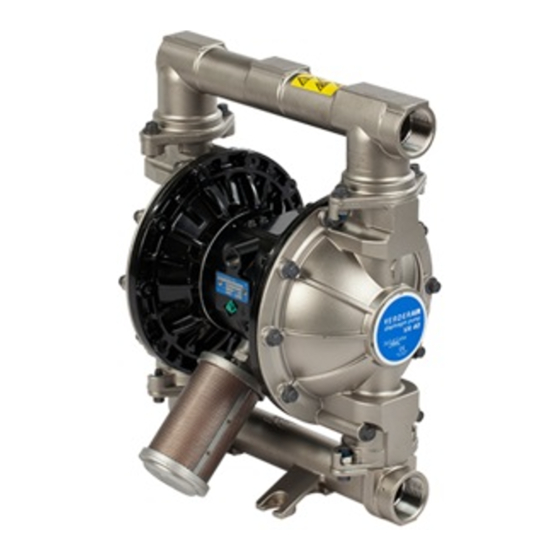
Parts
Aluminum Model Shown
829.4334
Rev. R
3263B
Advertisement
Table of Contents

Subscribe to Our Youtube Channel
Related Manuals for VERDER VA 40 HP


Summary of Contents for VERDER VA 40 HP
- Page 1 Rev. R READ AND RETAIN FOR REFERENCE INSTRUCTIONS ALUMINIUM AND STAINLESS STEEL V E R D E R AIR VA 40 HP Air-Operated Diaphragm Pumps 8.3 bar Maximum Fluid Working Pressure 8.3 bar Maximum Air Input Pressure * NOTE: Refer to the Pump Listing on page 22 to determine the Model No.
-
Page 2: Table Of Contents
D This equipment is for professional use only. D Read all instruction manuals, tags, and labels before operating the equipment. D Use the equipment only for its intended purpose. If you are not sure, call VERDER After Sales Service. D Do not alter or modify this equipment. - Page 3 Warning TOXIC FLUID HAZARD Hazardous fluid or toxic fumes can cause serious injury or death if splashed in the eyes or on the skin, inhaled, or swallowed. D Know the specific hazards of the fluid you are using. D Store hazardous fluid in an approved container. Dispose of hazardous fluid according to all local, state, and national guidelines.
-
Page 4: Installation
The Typical Installation shown in Fig. 2 is only a guide for selecting and installing system components. Contact your VERDER Customer Service for assistance in plan- ning a system to suit your needs. D Pump: Connect a ground wire and clamp as shown in Always use Genuine VERDER Parts and Accessories. - Page 5 Installation Install a grounded, flexible air hose (A) between the Mountings accessories and the 1/2 npt(f) pump air inlet (N). See Fig. 3. Use a minimum 13 mm ID air hose. Screw an air Caution line quick disconnect coupler (D) onto the end of the air hose (A), and screw the mating fitting into the pump air The pump exhaust air may contain contaminants.
- Page 6 Installation FLOOR MOUNT TYPICAL INSTALLATION Air Supply Hose Bleed-Type Master Air Valve (required for pump) Air Regulator Air Line Quick Disconnect Master Air Valve (for accessories) Air Line Filter G Fluid Suction Hose Fluid Supply Fluid Drain Valve (required) Fluid Shutoff Valve Fluid Hose 1–1/2 in.
- Page 7 Installation Changing the Orientation of the Fluid Inlet and Fluid Pressure Relief Valve Outlet Ports Caution The pump is shipped with the fluid inlet (R) and outlet (S) ports facing the same direction. See Fig. 3. To change the Some systems may require installation of a pressure relief orientation of the inlet and/or outlet port: valve at the pump outlet to prevent overpressurization and rupture of the pump or hose.
- Page 8 Installation The air exhaust port is 3/4 npt(f). Do not restrict the air ex- Air Exhaust Ventilation haust port. Excessive exhaust restriction can cause erratic pump operation. Warning FIRE AND EXPLOSION HAZARD To provide a remote exhaust: Be sure to read and follow the warnings and precautions regarding TOXIC FLUID HAZARD, and FIRE OR EXPLOSION HAZARD on page 3, before operating this...
-
Page 9: Operation
Operation Be sure the pump is properly grounded. Refer to Pressure Relief Procedure Grounding on page 4. Warning Check all fittings to be sure they are tight. Be sure to use a compatible liquid thread sealant on all male threads. PRESSURIZED EQUIPMENT HAZARD Tighten the fluid inlet and outlet fittings securely. -
Page 10: Maintenance
Maintenance Lubrication Tightening Threaded Connections The air valve is designed to operate unlubricated, however if Before each use, check all hoses for wear or damage, and lubrication is desired, every 500 hours of operation (or replace as necessary. Check to be sure all threaded connec- monthly) remove the hose from the pump air inlet and add tions are tight and leak-free. - Page 11 Notes 829.4334...
-
Page 12: Troubleshooting
Troubleshooting Relieve the pressure before checking or servicing the Warning equipment. To reduce the risk of serious injury whenever you are instructed to relieve pressure, always follow the Pressure Check all possible problems and causes before Relief Procedure on page 9. disassembling the pump. - Page 13 Troubleshooting PROBLEM CAUSE SOLUTION Fluid in exhaust air. Diaphragm ruptured. Replace. See pages 17–19. Loose diaphragm shaft bolt (107). Tighten or replace. See pages 17–19. Damaged o-ring (108). Replace. See pages 17–19. Pump exhausts excessive air at stall. Worn air valve block (7), o-ring (6), Repair or replace.
-
Page 14: Service
Service Repairing the Air Valve Tools Required † D Torque wrench D Torx (T20) screwdriver or 7 mm socket wrench D Needle-nose pliers D O-ring pick D Lithium base grease NOTE: Air Valve Repair Kit 819.4274 is available. Refer to page 23. - Page 15 Service Reassembly Insert narrow end first. Grease. Install with lips facing narrow end of piston (11). If you removed the bearings (12, 15), install new ones as explained on page 20. Reassemble the fluid section. Insert wide end first. Install the valve plate seal (9†) into the groove at the †...
-
Page 16: Ball Check Valve Repair
Service Ball Check Valve Repair Torque to 14–17 NSm. Arrow (A) must point toward outlet manifold (103). Tools Required Not used on some models. D Torque wrench Beveled seating surface must face ball (301). D 13 mm socket wrench D O-ring pick Disassembly NOTE: A Fluid Section Repair Kit is available. -
Page 17: Diaphragm Repair
Service Diaphragm Repair Disassembly NOTE: A Fluid Section Repair Kit is available. Refer to page 23 to order the correct kit for your pump. Parts Tools Required included in the kit are marked with an asterisk, for example (401*). Use all the parts in the kit for the best results. - Page 18 Service Loosen but do not remove the diaphragm shaft Install the fluid side diaphragm plate (105) on the bolts (107), using a 15 mm socket wrench (1 in. on stain- bolt so the rounded side faces in, toward the dia- less steel models) on both bolts.
- Page 19 Service 402* 403* 401* 03274 03275 Cutaway View, with Diaphragms in Place Cutaway View, with Diaphragms Removed 401* 403* 108* Lips face out of housing (1). Rounded side faces diaphragm (401). Air Side must face center housing (1). Grease. Apply medium-strength LoctiteR or equivalent. Torque to 27–34 NSm at 100 rpm maximum.
-
Page 20: Bearing And Air Gasket Removal
Service Remove the air cover gaskets (22). Always replace the Bearing and Air Gasket Removal gaskets with new ones. Tools Required Use a bearing puller to remove the diaphragm shaft D Torque wrench bearings (19), air valve bearings (12) or pilot pin bear- ings (15). - Page 21 Service Insert bearings tapered end first. Press-fit bearings flush with surface of center housing (1). Torque to 15–17 NSm. Detail of Air Valve Bearings 03277 03278B Fig. 13 829.4334...
-
Page 22: Pump Listing
Pump Listing VERDERAIR VA 40 Aluminium and Stainless Steel pumps, Series B Your Model No. is marked on the pump’s serial plate. The listing of existing VERDERAIR VA 40 pumps is below: FluidSect Part No. Seats Balls Diaphragms Section Á Á Á Á... -
Page 23: Repair Kit Listing
Service Insert bearings tapered end first. Press-fit bearings flush with surface of center housing (1). Torque to 15–17 NSm. Detail of Air Valve Bearings 03277 03278B Fig. 13 829.4334... -
Page 24: Parts
Parts Air Motor Parts List Fluid Section Parts List Fluid Ref. Section Ref. Part No. Description Material Part No. Description 819.4275 HOUSING, center; alum. 819.0226 COVER, fluid; aluminum 819.7102 HOUSING, center; stainless steel 819.6980 MANIFOLD, inlet; aluminum 819.4276 COVER, air valve; alum. 819.0228 MANIFOLD, outlet;... - Page 25 Parts Drawing † †10 6† †17 7† †18 9† 17† 110Y 10† 301* 402* 201* 202* Aluminum Model Shown 401* 108* 403* Not used on some models. Used on PTFE models only. *301 *201 * These parts are included in the Pump Repair Kit, which may only be purchased as a kit.
- Page 26 Parts Seat Parts List 201* 819.4355 SEAT; polypropylene Seat Ref. Material Part No. Description Closing disc 829.4349 201* 819.4349 SEAT; 316 stainless steel Closing disc 829.4349* 202* 819.4350 O-RING; PTFE 202* 819.4350 O-RING; PTFE 201* 819.4351 SEAT; 17-4 stainless steel –...
- Page 27 Parts Diaphragm Parts List 401* 819.7119 DIAPHRAGM; Buna–N Dia- phragm Ref. 402* 819.4284 PACKING, u-cup; – Material Part No. Description Buna–N 401* 819.4363 DIAPHRAGM, 401* 819.7132 DIAPHRAGM; Viton backup; Hytrel 402* 819.4284 PACKING, u-cup; 402* 819.4284 PACKING, u-cup; nitrile nitrile 403* 819.4364 DIAPHRAGM;...
-
Page 28: Dimensions
Dimensions FRONT VIEW SIDE VIEW 197 mm Port Diameter: 132.5 mm 44.5 mm 1/2 npt(f) Air Inlet 3/4 npt(f) Air Exhaust 268 mm 45° 38 mm 152.5 mm 152.5 mm 11.5 mm 379.5 mm 265.5 mm 7438B PUMP MOUNTING HOLE PATTERN Dimension Aluminum Pump Stainless Steel Pump... -
Page 29: Technical Data And Performance Chart
Technical Data 16.8 bar Maximum Fluid Working Pressure16.8 bar ....Fluid Inlet Size......1–1/2 in. -
Page 30: Customer Services/Guarantee
GUARANTEE All VERDER pumps are warranted to the original user against defects in workmanship or materials under normal use (rental use excluded) for two years after purchase date. This warranty does not cover failure of parts or components due to normal wear, damage or failure which in the judgement of VERDER arises from misuse. - Page 31 94/9/EC ATEX Directive (Ex II 2 G EEx c IIA T6) EN 292 EN 1127–1 EN 13463–1 ISO 9614–1 0359 12January2005 Frank Meersman 12January2005 DIRECTOR (Print) Verder Ltd. Whitehouse street Part No. : 819.5960 Leeds LS10 1AD Great Britain 819.4334...
- Page 32 Austria Germany Poland VERDER Ges. mbH Austria VERDER Deutschland GmbH VERDER Polska Sp. z o.o Perfektasstrasse 86 Rheinische Straße 43 ul. Kamienskiego 201-219 A-1232 Wien PO Box 1739 PL-51-124 Wroclaw, Polska Tel. 0222-8651074-0 D-42781 Haan Tel. 0 71726158 w.e.w. 59 Fax 0222-8651076 Tel.
Need help?
Do you have a question about the VA 40 HP and is the answer not in the manual?
Questions and answers