Table of Contents
Advertisement
Quick Links
INSTRUCTIONS – PARTS LIST
CONDUCTIVE POLYPROPYLENE*, POLYPROPYLENE AND PVDF
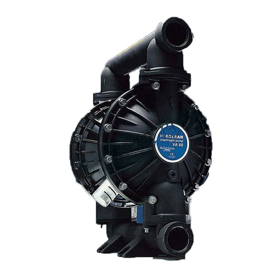
VERDERAIR VA 50
Air-Operated
Diaphragm Pumps
For fluid transfer applications. For professional use only.
8.3 bar Maximum Fluid Working Pressure
8.3 bar Maximum Air Input Pressure
Important Safety Instructions
Read all warnings and instructions in this manual.
Save these instructions.
Patent No.
CN ZL941026434.4
FR 9408894
JA 35107270
US 5,368,452
Ex h IIC 66°C...135°C Gb
Ex h IIIC T135°C Db
*Applies only to pumps with
conductive polypropylene fluid
sections.
*
II 2 GD
819.4496
Rev. ZAL
EN
04613B
Advertisement
Table of Contents

Subscribe to Our Youtube Channel
Related Manuals for VERDER VA 50


Summary of Contents for VERDER VA 50
- Page 1 INSTRUCTIONS – PARTS LIST CONDUCTIVE POLYPROPYLENE*, POLYPROPYLENE AND PVDF VERDERAIR VA 50 Air-Operated 819.4496 Rev. ZAL Diaphragm Pumps For fluid transfer applications. For professional use only. 8.3 bar Maximum Fluid Working Pressure 8.3 bar Maximum Air Input Pressure Important Safety Instructions Read all warnings and instructions in this manual.
-
Page 2: Table Of Contents
Table of Contents Symbols ........4 Service ........16 Installation . - Page 3 Configuration Number Matrix Check the identification plate (ID) for the 15–digit Configuration Number of your pump. Use the following matrix to define the components of your pump. Sample Configuration Number: VA50PA – SS TF TF FE 00 VA50 Fluid Section Air Section Seats Checks...
-
Page 4: Symbols
• Read all instruction manuals, tags, and labels before operating the equipment. • Use the equipment only for its intended purpose. If you are not sure, call VERDER After Sales Service. • Do not alter or modify this equipment. •... - Page 5 Warning TOXIC FLUID HAZARD Hazardous fluid or toxic fumes can cause serious injury or death if splashed in the eyes or on the skin, inhaled, or swallowed. • Know the specific hazards of the fluid you are using. • Store hazardous fluid in an approved container. Dispose of hazardous fluid according to all local, state, and national guidelines.
-
Page 6: Installation
VERDER Customer Service for assistance FIRE AND EXPLOSION in planning a system to suit your needs. HAZARD Always use Genuine VERDER Parts and Accessories. This pump must be grounded. Before Be sure all accessories are adequately sized and operating the pump, ground the system pressure-rated to meet the system’s requirements. - Page 7 Installation • All solvent pails used when flushing, according to local Grounding (continued) code. Use only metal pails, which are conductive. Do not place the pail on a non-conductive surface, such as To reduce the risk of static sparking, ground the pump and paper or cardboard, which interrupts the grounding all other equipment used or located in the pumping area.
- Page 8 Installation Air Line Locate one bleed-type master air valve (B) close to the pump and use it to relieve trapped air. See the Warning at left. Locate the other master air Warning valve (E) upstream from all air line accessories and use it to isolate them during cleaning and A bleed-type master air valve (B) is required in your system repair.
- Page 9 Installation Mountings If the fluid inlet pressure to the pump is more than 25% of the outlet working pressure, the ball check valves will not close fast enough, resulting in inefficient pump Caution operation. The pump exhaust air may contain contaminants. Ventilate At inlet fluid pressures greater than 1.05 bar, diaphragm to a remote area if the contaminants could affect your fluid life will be shortened.
- Page 10 Installation Flange Connections Place a flat washer (E) on each bolt (C). Refer to F . 3. The fluid inlet and outlet ports are 2 in. raised face, standard Align the holes in the gasket (B) and the pipe flange (A) 150 lb class pipe flanges.
- Page 11 Installation Changing the Orientation of the Fluid Inlet and Outlet Fluid Pressure Relief Valve Ports Caution The pump is shipped with the fluid inlet (R) and outlet (S) ports facing the same direction. See F . 4. To change the Some systems may require installation of a pressure relief orientation of the inlet and/or outlet port: valve at the pump outlet to prevent overpressurization and...
- Page 12 Installation Air Exhaust Ventilation The air exhaust port is 3/4 npt(f). Do not restrict the air exhaust port. Excessive exhaust restriction can cause erratic pump operation. Warning If the muffler (P) is installed directly to the air exhaust port, FIRE AND EXPLOSION apply PTFE thread tape or anti–seize lubricant to the muffler HAZARD threads before assembly.
-
Page 13: Operation
Operation Pressure Relief Procedure Be sure the pump is properly grounded. Refer to Grounding on page 6. Warning Check all fittings to be sure they are tight. Be sure to use a compatible liquid thread sealant on all male threads. PRESSURIZED EQUIPMENT HAZARD Tighten the fluid inlet and outlet fittings securely. -
Page 14: Maintenance
Maintenance Lubrication Tightening Threaded Connections The air valve is designed to operate unlubricated. However, Before each use, check all hoses for wear or damage, and if lubrication is desired, every 500 hours of operation (or replace as necessary. Check to be sure all threaded monthly) remove the hose from the pump air inlet and add connections are tight and leak-free. -
Page 15: Troubleshooting
Troubleshooting Relieve the pressure before checking or servicing the Warning equipment. Check all possible problems and causes before To reduce the risk of serious injury whenever you are disassembling the pump. instructed to relieve pressure, always follow the Pressure Relief Procedure on page 13. PROBLEM CAUSE SOLUTION... -
Page 16: Service
Service Repairing the Air Valve Tools Required • Torque wrench • Torx (T20) screwdriver or 7 mm socket wrench • Needle-nose pliers • O-ring pick • Lithium base grease NOTE: Air Valve Repair Kits 819.4274 (aluminum center housing models) and 819.0249 (stainless steel center housing models) are available. - Page 17 Service Reassembly Insert narrow end first. Install with lips facing If you removed the bearings (12, 15), install new ones as narrow end of piston (11). explained on page 23. Reassemble the fluid section. Grease. Insert wide end first. On aluminum center housing models, install the valve plate seal (9 ) into the groove at the bottom of the valve †...
-
Page 18: Ball Check Valve Repair
Service Ball Check Valve Repair Torque to 17–18 N•m. See Diaphragm Kits, page 29. Tools Required Arrow (A) must point toward outlet manifold (103). • Torque wrench Not used on some models. • 10 mm socket wrench • O-ring pick Disassembly NOTE: A Fluid Section Repair Kit is available. -
Page 19: Diaphragm Repair
Service Diaphragm Repair Warning Tools Required To reduce the risk of serious injury whenever you are • Torque wrench instructed to relieve pressure, always follow the Pressure Relief Procedure on page 13. • 13 mm socket wrench • Adjustable wrench Relieve the pressure. - Page 20 Service Unscrew one outer plate (105) from the diaphragm shaft Reassembly – Standard Diaphragms (24). Remove one diaphragm (401), and the inner plate Grease the shaft u-cup packings (402*) and install them (104). See F . 13. so the lips face out of the housing (1). See F .
- Page 21 Service Reassembly – Overmolded Diaphragms Assemble the other diaphragm assembly to the shaft as explained in step 2. This diaphragm will be lifted off the air cover at this point. WARNING Supply the pump with low pressure air (less than 0.5 bar To reduce the risk of serious injury, including amputation, [0.05 MPa, 7 psi]).
- Page 22 Service 402* 403* 401* 03982 04708 Cutaway View, with Diaphragms in Place Cutaway View, with Diaphragms Removed 401* 403* Lips face out of housing (1). Air Side must face center housing (1). Grease. Used on Models with two–piece PTFE diaphragms only.
-
Page 23: Bearing And Air Gasket Removal
Service Bearing and Air Gasket Removal Remove the air cover gaskets (22). Always replace the gaskets with new ones. Tools Required Use a bearing puller to remove the diaphragm shaft • Torque wrench bearings (19), air valve bearings (12) or pilot pin bearings (15). - Page 24 Service Insert bearings tapered end first. Press-fit bearings flush with surface of center housing (1). Torque to 15–17 N•m. 16 H Detail of Air Valve Bearings 03951 03952B . 14 _______________________________________________________________________________________ 819.4496...
-
Page 25: Repair Kit Listing
819.0397 – VA 50 HD Overmolded PTFE repair kit 819.0398 – VA 50 HD Overmolded PTFE repair kit with new air–side diaphragm plates NOTE: Heavy–duty overmolded diaphragms require new air–side diaphragm plates. If a bolt–through diaphragm was in use, you must purchase 819.0398, the kit that includes the new plates. - Page 26 Parts Air Motor Parts List Fluid Section Parts List Fluid Ref. Section Ref. Part No. Description Material 819.4275 HOUSING, center; alum. 819.4497 COVER, fluid; 819.0247 HOUSING, center; stainless polypropylene steel 819.0279 COVER, fluid; 819.4276 COVER, air valve; alum. conductive polypropylene 819.0259 COVER, air valve;...
- Page 27 Fluid Section Parts List (continued) 819.4501 COVER, fluid; PVDF 819.4502 MANIFOLD, inlet; PVDF 819.4503 MANIFOLD, outlet; PVDF 819.4301 PLATE, air side; aluminum 819.4504 PLATE, fluid side; PVDF 819.4375 SCREW; M8 x 1.25; 70 mm; sst 819.4491 SCREW; M10 x 1.50; 60 mm; sst 819.9753 SCREW;...
- Page 28 Parts 401* 301* 403* 201* 202* *402 *301 *201 202* 04622D Not used on some models. These parts are included in the Pump Repair Kit, which may only be purchased as a kit. Refer to the Repair Kit Listing on page 27 to determine the correct kit for your pump.
- Page 29 Parts Valve Seat Kits Diaphragm Kits Seat Ref. Diaphragm Ref. Material Kit No. Description Material Kit No. Description 819.0041 VA50P BN,--,--,-- 819.0043 VA50P --,--,BN,-- Not required Included in 819.4613 VA50P HY,--,--,-- above kit Not required 819.4510 VA50P --,--,HY,-- 819.4718 VA50P KY,--,--,TF Included in Included in above kit...
- Page 30 Torque Sequence Always follow torque sequence when instructed to torque fasteners. Left/Right Fluid Covers Outlet Manifold Torque bolts to 22–25 N•m. Torque bolts to 17–18 N•m BOTTOM VIEW SIDE VIEW Inlet Manifold Torque bolts to 17–18 N•m BOTTOM VIEW 819.4496...
- Page 31 Dimensions FRONT VIEW 1/2 npt(f) 3/4 npt(f) Air Inlet Air Exhaust (muffler included) 7441B SIDE VIEW Port Diameter: 159 mm 56 mm Dimensions B, C, F, G, H, and M can vary by up to 1/4 in. (6.3 mm) depending on the seat and diaphragm Flange Diameter: 152.5 mm material fitted in the pump.
- Page 32 Dimensions Dimension SST Center SST Center Aluminum Aluminum Polypropylene PVDF Cover Center Center Cover Polypropylene PVDF Cover Cover 11.0 11.0 11.0 11.0 13.7 13.6 13.7 13.6 19.7 19.6 19.7 19.6 19.2 19.1 19.2 19.1 22.7 22.6 22.7 22.6 25.7 25.6 25.7 25.6 819.4496...
- Page 33 Technical Data Maximum Fluid Working Pressure 8.3 bar Fluid Outlet Size. 2 in. Raised Face Flange Air Pressure Operating Range 1.4–8.3 bar ANSI/DIN 50 Flange 2 in. (50 mm) Maximum Air Consumption 4.9 N m /min Wetted Parts Vary by Model. Refer to pages 26–29 Air Consumption Non-wetted External Parts Aluminum,...
- Page 34 Performance Chart Example of Finding Pump Air Consumption and Air Pressure at a Specific Fluid Delivery and Discharge Head: To supply 227 liters fluid flow (horizontal scale) at 2.8 bar discharge head pressure (vertical scale) requires approximately 1.68 N m /min air consumption at 4.9 bar inlet air pressure.
- Page 35 GUARANTEE All VERDER pumps are warranted to the original user against defects in workmanship or materials under normal use (rental use excluded) for two years after purchase date. This warranty does not cover failure of parts or components due to normal wear, damage or failure which in the judgement of VERDER arises from misuse.
- Page 36 é 819.4496...
Need help?
Do you have a question about the VA 50 and is the answer not in the manual?
Questions and answers