Table of Contents
Advertisement
Quick Links
www.ti.com
EVM User's Guide: MCF8329EVM
MCF8329 Evaluation Module
Description
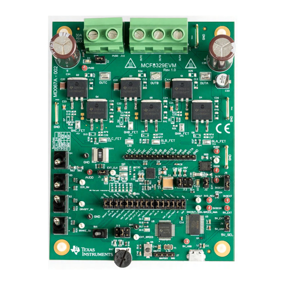
The MCF8329EVM allows users to evaluate the
performance of a MCF8329 motor driver. The EVM
includes an onboard FTDI chip to convert USB
communication, from the micro-USB connector, into
UART. An onboard MSP430FR2355 microcontroller
(MCU) translates the UART communication into either
control signals or SPI formatted data, which is
sent to the MCF8329 device. There are many user-
selectable jumpers, resistors, connectors, and test
points to assist with evaluating the many features of
the MCF8329 IC and the configurable device-specific
settings.
Get Started
1. Download the latest design files from the
MCF8329EVM tool page
2. Download the latest version of the Motor Studio
GUI and firmware from the
on ti.com
SLLU373 – NOVEMBER 2023
Submit Document Feedback
on ti.com
Motor Studio tool page
MCF8329EVM (Top View)
Copyright © 2023 Texas Instruments Incorporated
Features
•
GUI software to simplify the MCx tuning process
and performance evaluation
•
MCU-to-MCx shunt jumper header with removable
shunts to disconnect main signals going to the
motor driver IC from the MCU
– The shunts can be removed if the user desires
to control the MCF8329 IC with an external
MCU or to use the EVM MCU to control an
external MCF8329 IC
Applications
•
Cordless vacuum
•
Cordless garden tools
•
CPAP machine
•
Ventilator
•
Server fans
Description
MCF8329 Evaluation Module
1
Advertisement
Table of Contents

Related Manuals for Texas Instruments MCF8329EVM


Summary of Contents for Texas Instruments MCF8329EVM
- Page 1 Description EVM User's Guide: MCF8329EVM MCF8329 Evaluation Module Description Features The MCF8329EVM allows users to evaluate the • GUI software to simplify the MCx tuning process performance of a MCF8329 motor driver. The EVM and performance evaluation includes an onboard FTDI chip to convert USB •...
-
Page 2: Kit Contents
USB A Male-to-USB B Micro Male Cable 1.3 Specification The MCF8329EVM can support voltages up to 60 V and currents up to 30 A. To prevent damage to both the IC and the EVM, confirm that these voltage and current specifications are not exceeded. - Page 3 2 Hardware 2.1 Quick Start Guide The MCF8329EVM requires a power supply source, which has a recommended operating range from a 4.5-V to 60-V. To setup and power the EVM, follow the sequence below: 1. Connect motor phases to A, B, and C on connector J11.
-
Page 4: Hardware Setup
2.2 Hardware Setup The hardware required to run the motor is the MCF8329EVM, a micro-USB cable, and a power supply with a DC output from 4.5-V to 60-V. Follow these steps to start up the MCF8329EVM: 1. Connect the DC power supply to header J10. Connect to PVDD and GND. -
Page 5: Connection Details
Hardware 2.4 Connection Details Figure 2-3 outlines which connections must be made to the MCF8329EVM in order to spin a 3-phase sensorless brushless-DC motor. Connect a 4.5-V to 60-V power supply to the PVDD and GND terminals on connector J10. - Page 6 The 32-pin shunt jumper bridge J9 ties all signals between the microcontroller and MCF8329 IC. These jumpers can be inserted or removed as needed to isolate the microcontroller from the gate driver. This allows for microcontroller signal debugging or using the MCF8329EVM as a standalone gate driver with an external microcontroller.
-
Page 7: Led Lights
2.6 LED Lights The MCF8329EVM has 5 status LEDs that provide the status of power supplies and functions of the evaluation module. By default, the PVDD LED and AVDD LED lights up when the board is powered and the program has been flashed onto the microcontroller. -
Page 8: User Configurable Settings
Hardware www.ti.com 2.7 User Configurable Settings The MCF8329EVM includes a variety of user-selectable jumpers, switches, and resistors on the entirety of the evaluation board to configure settings. Table 2-2 summarizes all of these configurable settings. Table 2-2. Description of User-Selectable Settings on MCF8329EVM (Default in Bold) - Page 9 Hardware Table 2-2. Description of User-Selectable Settings on MCF8329EVM (Default in Bold) (continued) Designator Setting Name Description Layer Position Function Configure SPEED/Wake pin to Left SPEED mode and DCAOUT/SOx/ SPEED/ANA pin to DACOUT mode Configure SPEED/WAKE pin to Configure SPEED/WAKE pin to...
- Page 10 PC and the MCF8329 device for configuring various device settings and reading fault diagnostic information. The MCF8329EVM is supported on the Motor Studio GUI which can be used to configure the MCF8329 though this communication interface. The Motor Studio GUI simplifies the tuning process of the MCF8329 by offering guided tuning instructions, a virtual oscilloscope for real-time variable monitoring, and more.
- Page 11 5. Select the folder created in step 1 by extracting the Motor Studio firmware. 6. Import the project into your workspace as shown in Figure 3-2 Figure 3-2. MSP430FR2355 Interface Firmware Code in Code Composer Studio SLLU373 – NOVEMBER 2023 MCF8329 Evaluation Module Submit Document Feedback Copyright © 2023 Texas Instruments Incorporated...
- Page 12 1. Remove the GND, 3V3, SBWTDIO, and SBWTCK jumpers from the MSP430 LaunchPad. 2. Connect the top pins on the eZ-FET side of the LaunchPad of the GND, 3V3, SBWTDIO, SBWTCK signals to their respective pins on J7 of the MCF8329EVM as shown in Table 3-1 Figure 3-3.
- Page 13 DRVOFF MSP430FR2355TPTR DRVOFF_SW Populate jumpers to communicate onboard MSP430FR2355 to the MCx8329A or depopulate jumpers to use standalone MSP430 or MCx8329A. Figure 4-1. Interfaces SLLU373 – NOVEMBER 2023 MCF8329 Evaluation Module Submit Document Feedback Copyright © 2023 Texas Instruments Incorporated...
-
Page 14: Status Leds
330pF 100V Route as differential pair Kelvin connection to shunt 0.001 0.01uF 330pF 100V Figure 4-3. MOSFETs and Power Stage MCF8329 Evaluation Module SLLU373 – NOVEMBER 2023 Submit Document Feedback Copyright © 2023 Texas Instruments Incorporated... -
Page 15: Main Supply Input
OUTB OUTC OUTC TP25 MOTOR_OUT Motor Phase Connector 35A rated VREG- External MOSFET Voltage Regulator PVDD GCTRL VREG_EXT_FET 2000pF Figure 4-4. Power and Connectors SLLU373 – NOVEMBER 2023 MCF8329 Evaluation Module Submit Document Feedback Copyright © 2023 Texas Instruments Incorporated... -
Page 16: Pcb Layouts
Hardware Design Files www.ti.com 4.2 PCB Layouts Figure 4-5. EVM Board Dimensions MCF8329 Evaluation Module SLLU373 – NOVEMBER 2023 Submit Document Feedback Copyright © 2023 Texas Instruments Incorporated... - Page 17 Hardware Design Files Figure 4-6. EVM Top Overlay SLLU373 – NOVEMBER 2023 MCF8329 Evaluation Module Submit Document Feedback Copyright © 2023 Texas Instruments Incorporated...
- Page 18 Hardware Design Files www.ti.com Figure 4-7. EVM Top Layer MCF8329 Evaluation Module SLLU373 – NOVEMBER 2023 Submit Document Feedback Copyright © 2023 Texas Instruments Incorporated...
- Page 19 Hardware Design Files Figure 4-8. EVM Signal Layer 1 SLLU373 – NOVEMBER 2023 MCF8329 Evaluation Module Submit Document Feedback Copyright © 2023 Texas Instruments Incorporated...
- Page 20 Hardware Design Files www.ti.com Figure 4-9. EVM Signal Layer 2 MCF8329 Evaluation Module SLLU373 – NOVEMBER 2023 Submit Document Feedback Copyright © 2023 Texas Instruments Incorporated...
- Page 21 Hardware Design Files Figure 4-10. EVM Bottom Layer SLLU373 – NOVEMBER 2023 MCF8329 Evaluation Module Submit Document Feedback Copyright © 2023 Texas Instruments Incorporated...
- Page 22 Hardware Design Files www.ti.com Figure 4-11. EVM Bottom Overlay MCF8329 Evaluation Module SLLU373 – NOVEMBER 2023 Submit Document Feedback Copyright © 2023 Texas Instruments Incorporated...
- Page 23 H5, H6, H7, H8 Screw NY PMS 440 0025 PH B&F Fastener Supply Philips panhead J1, J2, J3 Header, 100mil, 2x1, Gold, TH 2x1 Header TSW-102-07-G-S Samtec SLLU373 – NOVEMBER 2023 MCF8329 Evaluation Module Submit Document Feedback Copyright © 2023 Texas Instruments Incorporated...
- Page 24 ERA-3ARW103V Panasonic R24, R48, R52, R53 0603 R28, R29, R30, R34, RES, 10, 5%, 0.1 W, AEC-Q200 Grade 0, 0603 CRCW060310R0JNEA Vishay-Dale R35, R36 MCF8329 Evaluation Module SLLU373 – NOVEMBER 2023 Submit Document Feedback Copyright © 2023 Texas Instruments Incorporated...
- Page 25 5016 Keystone Sensorless Field Oriented Control (FOC) Three- WQFN36 MCF8329A0REER Texas Instruments phase BLDC Gate Driver USB to Serial UART, SSOP28 SSOP28 FT232RL FTDI SLLU373 – NOVEMBER 2023 MCF8329 Evaluation Module Submit Document Feedback Copyright © 2023 Texas Instruments Incorporated...
- Page 26 Bit 24 MHz 32 KB (32K x 8) FRAM 48-LQFP LQFP48 MSP430FR2355TPTR Texas Instruments (7x7) Resonator, 4 MHz, 39 pF, AEC-Q200 Grade 1, 4.5x1.2x2 mm CSTCR4M00G55B-R0 MuRata MCF8329 Evaluation Module SLLU373 – NOVEMBER 2023 Submit Document Feedback Copyright © 2023 Texas Instruments Incorporated...
-
Page 27: Additional Information
, Code Composer Studio ™ , MSP-EXP430FR2355 LaunchPad ™ , and MSP430 ™ are trademarks of Texas Instruments. All trademarks are the property of their respective owners. SLLU373 – NOVEMBER 2023 MCF8329 Evaluation Module Submit Document Feedback Copyright © 2023 Texas Instruments Incorporated... -
Page 28: Important Notice
TI products. TI’s provision of these resources does not expand or otherwise alter TI’s applicable warranties or warranty disclaimers for TI products. TI objects to and rejects any additional or different terms you may have proposed. IMPORTANT NOTICE Mailing Address: Texas Instruments, Post Office Box 655303, Dallas, Texas 75265 Copyright © 2023, Texas Instruments Incorporated...
Need help?
Do you have a question about the MCF8329EVM and is the answer not in the manual?
Questions and answers