Texas Instruments MSP430 User Manual
Gang programmer
Hide thumbs
Also See for MSP430:
- Manual (413 pages) ,
- Student manual (398 pages) ,
- User manual (194 pages)
Table of Contents
Advertisement
Quick Links
Download this manual
See also:
User Manual
Advertisement
Table of Contents

Related Manuals for Texas Instruments MSP430


Summary of Contents for Texas Instruments MSP430
- Page 1 MSP430 Gang Programmer (MSP-GANG430) User's Guide Literature Number: SLAU101O March 2003 – Revised May 2010...
- Page 2 SLAU101O – March 2003 – Revised May 2010 Copyright © 2003–2010, Texas Instruments Incorporated...
-
Page 3: Table Of Contents
Description of the Gang430.ini File ................2.1.6 Target Connector Functional Check ............Programming MSP430 Flash Devices in Stand-Alone Mode ........Programming MSP430 Flash Devices With User-Configured UART Handler ............Programming the MSP430 Devices With GANG430.DLL .......................... Firmware ......................... Commands .................... - Page 4 Hex File Formats ....................Intel Hex Object Format ......................TI-txt File Format ....................Frequently Asked Questions ........................FAQs ..................... Preproduction Checklist ......................Document Revision History Contents SLAU101O – March 2003 – Revised May 2010 Copyright © 2003–2010, Texas Instruments Incorporated...
- Page 5 MSP-GANG430 Hardware Specifications ..............5-2. MSP-GANG430 Target Connector Signal Functions ................... 5-3. MSP-GANG430 Signal Levels ..............C-1. Preproduction Checklist for the Gang Programmer SLAU101O – March 2003 – Revised May 2010 List of Figures Copyright © 2003–2010, Texas Instruments Incorporated...
- Page 6 All trademarks are the property of their respective owners. List of Tables SLAU101O – March 2003 – Revised May 2010 Copyright © 2003–2010, Texas Instruments Incorporated...
-
Page 7: Preface
Support for the MSP430 device and the MSP-GANG430 is provided by the Texas Instruments Product Information Center (PIC). Contact information for the PIC can be found on the Texas Instruments web site at www.ti.com. Additional device-specific information can be found on the MSP430 web site at www.ti.com/msp430. - Page 8 Read This First SLAU101O – March 2003 – Revised May 2010 Copyright © 2003–2010, Texas Instruments Incorporated...
-
Page 9: Introduction, Installation, And Setup
This chapter introduces the MSP-GANG430 and guides you through the installation of the software and hardware..........................Topic Page ...................... Introduction ..................Software Installation ..................Hardware Installation SLAU101O – March 2003 – Revised May 2010 Introduction, Installation, and Setup Copyright © 2003–2010, Texas Instruments Incorporated... -
Page 10: Introduction
MSP-GANG430 can be brought out to each of the target devices via an MSP430-standard JTAG connector. The circuit could easily be modified to connect the signals to the target device pins directly (via a socket) if a traditional gang programmer is desired. -
Page 11: Hardware Installation
3. Attach the expansion board to the 25-pin Sub-D connector on the MSP-GANG430. The expansion board provides connectivity for up to eight targets, using the included 14-pin cables. The target MSP430 flash devices can be in stand-alone sockets or can be on an application’s PCB, and they are accessed via the JTAG signals. -
Page 12: Msp-Gang430 Gang Programmer
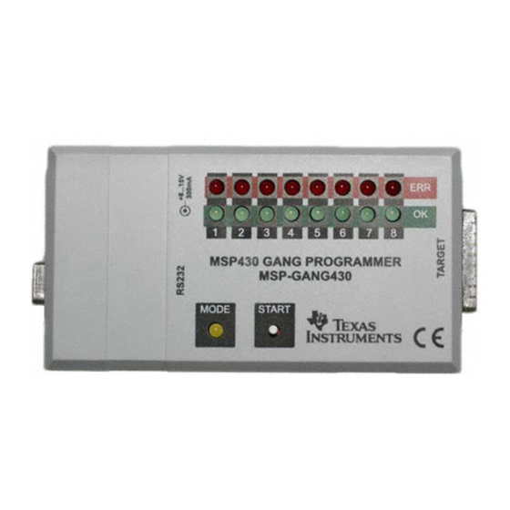
Power supply MSP430 Gang Programmer MSP-GANG430 MODE START RS232 JTAG connector for eight from MSP430 devices Figure 1-1. MSP-GANG430 Gang Programmer Introduction, Installation, and Setup SLAU101O – March 2003 – Revised May 2010 Copyright © 2003–2010, Texas Instruments Incorporated... -
Page 13: Operation
Chapter 2 SLAU101O – March 2003 – Revised May 2010 Operation This chapter describes how to program MSP430 flash devices using the MSP-GANG430..........................Topic Page ..........Programming MSP430 Flash Devices Using the GUI ........Programming MSP430 Flash Devices in Stand-Alone Mode ..... -
Page 14: Programming Msp430 Flash Devices Using The Gui
1. Connect the MSP-GANG430 hardware and the targets as described in Section 1.3. 2. Click on the GANG430 icon located in the program group specified during installation of the software (the default group is ADT430). The MSP430 FLASH Gang Programmer GUI is displayed on the screen (see Figure 2-1). -
Page 15: Msp-Gang430 Gui
Programming MSP430 Flash Devices Using the GUI www.ti.com Figure 2-1. MSP-GANG430 GUI SLAU101O – March 2003 – Revised May 2010 Operation Copyright © 2003–2010, Texas Instruments Incorporated... -
Page 16: Description Of The Msp-Gang430 Gui
Programs the image buffer into the target’s flash memory Verify Compares the target’s flash memory and the image buffer Makes MSP430 devices secure after successful completion of the selected Secure Device operations (permanently disables device access through JTAG) Supplied by... -
Page 17: Status Messages
Programming MSP430 Flash Devices Using the GUI www.ti.com 2.1.3 Status Messages Table 2-2 shows the status messages that can be displayed in the MSP-GANG430 GUI during operation. Table 2-2. Status Messages Status Type Status Message Executing main process... Erasing image buffer... -
Page 18: Error Messages
Programming MSP430 Flash Devices Using the GUI www.ti.com 2.1.4 Error Messages Table 2-3 shows the error messages that can be displayed in the MSP-GANG430 GUI when an error occurs during operation. Table 2-3. Error Messages Error Type Error Message ERROR: Unable to read Target! ERROR: Unable to open COM port −... -
Page 19: Description Of The Gang430.Ini File
Section [User] The initial settings for the following parameters are in the [User] section and may be modified by the user. CaptionIndexed = 0 (default). The caption of the MSP-GANG430 GUI in the default state is MSP430 FLASH Gang Programmer. -
Page 20: Target Connector Functional Check
Programming MSP430 Flash Devices Using the GUI www.ti.com Table 2-4. Values for MiscErrors MiscErrors Description Operation successful FATAL ERROR: Image memory could be corrupted or erased ERROR: Main process parameters not yet set ERROR: Could not set target voltage (VCCT) − MSP_VCC_IN pin connected? 2.1.6 Target Connector Functional Check... -
Page 21: Programming Msp430 Flash Devices In Stand-Alone Mode
Enter 0x010A (0x0002 + 0x0008 + 0x0100) into Set Signal and click Execute. Programming MSP430 Flash Devices in Stand-Alone Mode The MSP-GANG430 supports a stand-alone mode of programming the target MSP430 flash devices. The programming options for the MSP-GANG430 while it operates in stand-alone mode are configured using the GUI. - Page 22 Operation SLAU101O – March 2003 – Revised May 2010 Copyright © 2003–2010, Texas Instruments Incorporated...
-
Page 23: Firmware
This chapter describes the firmware commands and protocol for controlling the MSP-GANG430 via its RS-232 serial communication interface..........................Topic Page ....................... Commands ................Firmware Interface Protocol ................. Synchronization Sequence ....................... Data Frame ..............Detailed Description of Commands SLAU101O – March 2003 – Revised May 2010 Firmware Copyright © 2003–2010, Texas Instruments Incorporated... -
Page 24: Commands
NOTE: The synchronization character is not part of the data frame described in Section 3.4. Data Frame The data frame format follows the TI MSP430 serial standard protocol (SSP) rules, extended with a preceding synchronization sequence (SS), as described in Section 3.3. The MSP-GANG430 is considered... -
Page 25: Frame Structure
CKH = INV [ B2 XOR B4 XOR … XOR Bn ] The example of the frame Execute Self Test with checksum: 0x80 0x35 0x06 0x06 0x00 0x00 0x00 0x00 0x00 0x00 0x79 0xCC SLAU101O – March 2003 – Revised May 2010 Firmware Copyright © 2003–2010, Texas Instruments Incorporated... -
Page 26: Data Frame Of Firmware Commands
All numbers are bytes in hexadecimal notation. ACK is sent by the MSP-GANG430. The synchronization sequence (TX = 0x80, RX = 0x90) is not part of the data frame. It must precede every frame. HDR: DATA_FRAME = 0x80 means data frame expected in accordance with TI MSP430 serial standard protocol (SSP). CMD:... -
Page 27: Detailed Description Of Commands
0x10: Executes programming of main memory 0x18: Executes programming of info and main memory 0x20: Executes verification of info and main memory 0x40: Makes MSP430 devices secure 0x80: Executes programming of RAM memory D2: Flags for target supply voltage VCC_MSP... -
Page 28: Start
D13 to D30 hold a zero-terminated character string representing the firmware file name; e.g., GANG430_100.TXT. 3.5.5 Erase Image The Erase Image command erases the entire image memory and verifies the erasure. Firmware SLAU101O – March 2003 – Revised May 2010 Copyright © 2003–2010, Texas Instruments Incorporated... -
Page 29: Load Image Block
The number of parameters depends on the memory model of the selected device. SLAU101O – March 2003 – Revised May 2010 Firmware Copyright © 2003–2010, Texas Instruments Incorporated... -
Page 30: Select Baud Rate
1: 19200 baud 2: 38400 baud 3: 57600 baud 4: 115200 baud The Select Baud Rate command takes effect (i.e., changes the baud rate) immediately. Firmware SLAU101O – March 2003 – Revised May 2010 Copyright © 2003–2010, Texas Instruments Incorporated... -
Page 31: Execute Self Test
3.5.15 Firmware Commands TI recommends against invoking commands that affect the firmware (such as Erase Firmware, Load Firmware Block, and Finalize Firmware), except from the MSP-GANG430 GUI. SLAU101O – March 2003 – Revised May 2010 Firmware Copyright © 2003–2010, Texas Instruments Incorporated... - Page 32 Firmware SLAU101O – March 2003 – Revised May 2010 Copyright © 2003–2010, Texas Instruments Incorporated...
-
Page 33: Dynamic Link Library Gang430.Dll
Dynamic Link Library GANG430.DLL This chapter describes the dynamic link library GANG430.DLL..........................Topic Page ................. GANG430.DLL Description ........... Return Values/Error Codes From GANG430.DLL SLAU101O – March 2003 – Revised May 2010 Dynamic Link Library GANG430.DLL Copyright © 2003–2010, Texas Instruments Incorporated... -
Page 34: Gang430.Dll Description
GANG430.DLL Description www.ti.com GANG430.DLL Description GANG430.DLL communicates with the MSP-GANG430 programmer unit and the connected MSP430 device(s). GANG430.INI must be in the same directory as GANG430.DLL. The configuration of the MSP-GANG430 should be done with the following sequence. InitCom // Open communication port... - Page 35 Valid baud rates are 9600, 19200, 38400, 57600, and 115200 baud. The default baud rate after initialization is 115200 baud. lpszComPort The name of the communication port: COM1...COM15 Example lFuncReturn = InitCom("COM1", 115200); SLAU101O – March 2003 – Revised May 2010 Dynamic Link Library GANG430.DLL Copyright © 2003–2010, Texas Instruments Incorporated...
- Page 36 ReleaseCom (void) This function is the counterpart to InitCom. It allows closing a communication with the Description MSP-GANG430 hardware. Example IFuncReturn = ReleaseCom(); Dynamic Link Library GANG430.DLL SLAU101O – March 2003 – Revised May 2010 Copyright © 2003–2010, Texas Instruments Incorporated...
- Page 37 1: 19200 baud 2: 38400 baud 3: 57600 baud 4: 115200 baud (default after power up) Example lFuncReturn = GangSelectBaudrate(2); // selects 38400 baud SLAU101O – March 2003 – Revised May 2010 Dynamic Link Library GANG430.DLL Copyright © 2003–2010, Texas Instruments Incorporated...
- Page 38 Clears (presets with 0xFF) the image memory of the MSP-GANG430 programming unit. Description Performs a succeeding erase check over the address range 0x1000 to 0xFFFFF. Example lFuncReturn = GangEraseImage(); Dynamic Link Library GANG430.DLL SLAU101O – March 2003 – Revised May 2010 Copyright © 2003–2010, Texas Instruments Incorporated...
- Page 39 Name of the file to be loaded (full path) or NULL if function is only called to set up the target device. lpszDeviceName Name of the device in file Gang430.ini. Take care of the <space> between MSP430 and Fxxx. Example lFuncReturn = GangLoadImage(FileName, "MSP430 F5529");...
- Page 40 Example GangLoadImage( file_1, "MSP430 F5529"); //download code GangAppendImage(); GangLoadImage( file_2, "MSP430 F5529"); //append code GangAppendImage(); GangLoadImage( file_3, "MSP430 F5529"); //append next code Dynamic Link Library GANG430.DLL SLAU101O – March 2003 – Revised May 2010 Copyright © 2003–2010, Texas Instruments Incorporated...
- Page 41 This function sets the active image. GANG430 supports two images. Description lImage Arguments 0 or 1, the image number. Default image number is 0. Example lFuncReturn = GangSelectImage(1); SLAU101O – March 2003 – Revised May 2010 Dynamic Link Library GANG430.DLL Copyright © 2003–2010, Texas Instruments Incorporated...
- Page 42 // executes programming of info and main memory F_VERIFY 0x0020 // executes verification of info and main memory F_SECURE_DEVICE 0x0040 // makes MSP430 devices secure F_PROGRAM_RAM 0x0080 // executes programming of ram memory F_ERASE_CHECK_INFO 0x0100 // executes erase check of info memory...
- Page 43 The time out in hundreds of milliseconds until the programming unit must respond. Example lFuncReturn = GangMainProcess(120); // with 12s time out SLAU101O – March 2003 – Revised May 2010 Dynamic Link Library GANG430.DLL Copyright © 2003–2010, Texas Instruments Incorporated...
- Page 44 D11 = LSByte D12 to D29 hold a zero-terminated character string representing the firmware file name (e.g., GANG430-120.TXT). Example lFuncReturn = GangGetResult(lpBuffer); Dynamic Link Library GANG430.DLL SLAU101O – March 2003 – Revised May 2010 Copyright © 2003–2010, Texas Instruments Incorporated...
- Page 45 Pointer points to a buffer that holds the data to be read/written. Example lFuncReturn = GangAccessTargetSFR(7, 0, 0x120, &lpData); // reads WDTCTL register of target 8 wordwise to lpData SLAU101O – March 2003 – Revised May 2010 Dynamic Link Library GANG430.DLL Copyright © 2003–2010, Texas Instruments Incorporated...
- Page 46 Pointer points to a buffer that holds the data to be programmed (the source data buffer). Example lFuncReturn = GangProgramTarget(7, 0x1000, 0x10, lpData); // programs 16 bytes exclusively into target 8 starting at address 0x1000 Dynamic Link Library GANG430.DLL SLAU101O – March 2003 – Revised May 2010 Copyright © 2003–2010, Texas Instruments Incorporated...
- Page 47 Example lFuncReturn = GangReadTarget(0, 0xF000, 0x1000, lpDest); // reads 4k bytes exclusively from target 1 starting at address 0xF000 into a buffer SLAU101O – March 2003 – Revised May 2010 Dynamic Link Library GANG430.DLL Copyright © 2003–2010, Texas Instruments Incorporated...
- Page 48 = GangReadTargetFile(7, 0xF000, 0x1000, FileName, 1); // reads 4k bytes exclusively from target 8 starting at address 0xF000 into a file with TI-txt format Dynamic Link Library GANG430.DLL SLAU101O – March 2003 – Revised May 2010 Copyright © 2003–2010, Texas Instruments Incorporated...
- Page 49 VCC_MSP output voltage is same as loaded by the GangLoadParameters function. Others VCC_MSP is set in hundreds of millivolts Example lFuncReturn = GangSetVccTarget(36); // Set target VCC to 3.6 V SLAU101O – March 2003 – Revised May 2010 Dynamic Link Library GANG430.DLL Copyright © 2003–2010, Texas Instruments Incorporated...
- Page 50 The time out in hundreds of milliseconds until the programming unit must respond. Example lFuncReturn = GangSelftest(60); // with 6s time out Dynamic Link Library GANG430.DLL SLAU101O – March 2003 – Revised May 2010 Copyright © 2003–2010, Texas Instruments Incorporated...
- Page 51 Determines logic high-level voltage of signals in hundreds of millivolts Example lFuncReturn = GangSetSignals(0x0400, 27); // VPP at pin 17 (TEST/VPP); VCC = 2.7 V SLAU101O – March 2003 – Revised May 2010 Dynamic Link Library GANG430.DLL Copyright © 2003–2010, Texas Instruments Incorporated...
- Page 52 Arguments Window handle of a status line hProgBar Window handle, especially of a progress bar Example lFuncReturn = InitProgress((long int)lpStatus->GetSafeHwnd(), (long int)lpProgress->GetSafeHwnd()); Dynamic Link Library GANG430.DLL SLAU101O – March 2003 – Revised May 2010 Copyright © 2003–2010, Texas Instruments Incorporated...
- Page 53 Determines the string associated with the error number. For invalid error numbers, a Description pointer to "Invalid error number!" is returned. lErrorNumber Arguments The error number Example lpszErrorString = GetErrorString(lFuncReturn); SLAU101O – March 2003 – Revised May 2010 Dynamic Link Library GANG430.DLL Copyright © 2003–2010, Texas Instruments Incorporated...
-
Page 54: Return Values/Error Codes From Gang430.Dll
No target device connected Code data saved to already used location (overwritten). Check code file_1 ERR_IMAGE_OVERWRITTEN and file_2 if contains data in the same locations. Dynamic Link Library GANG430.DLL SLAU101O – March 2003 – Revised May 2010 Copyright © 2003–2010, Texas Instruments Incorporated... -
Page 55: Hardware
Programming Times vs Code Size for the Gang Programmer ............Recommendations for Target Connections ............MSP-GANG430 Target Connector Signals ................MSP-GANG430 Schematics ..............MSP-GANG430 Component Locations ............Gang_Exp Target Expansion Board Layout SLAU101O – March 2003 – Revised May 2010 Hardware Copyright © 2003–2010, Texas Instruments Incorporated... -
Page 56: Specifications
NOTE: Using SpyBiWire mode requires approximately 3 seconds to program 2 KByte. As devices are programmed consecutively, the total time for eight devices is 24 seconds. Hardware SLAU101O – March 2003 – Revised May 2010 Copyright © 2003–2010, Texas Instruments Incorporated... -
Page 57: Recommendations For Target Connections
Recommendations for Target Connections www.ti.com Recommendations for Target Connections The following hardware connections are recommended when connecting the target MSP430 flash devices to the MSP-GANG430 without usage of the expansion board. • The VCC pins of all the targets must be tied together and connected to the positive terminal of the supply. -
Page 58: Pin Sub-D At Msp-Gang430
TDO/TDI8 TDO/TDI5 TDO/TDI7 TDO/TDI6 Figure 5-1. 25-Pin Sub-D at MSP-GANG430 VCC_MSP TDO/TDIx MSP_VCC_IN TDI/VPP TEST/VPP RESET Figure 5-2. 14-Pin Connector at End of Interconnect Cable Hardware SLAU101O – March 2003 – Revised May 2010 Copyright © 2003–2010, Texas Instruments Incorporated... -
Page 59: Msp-Gang430 Target Connector Signal Functions
The programming procedure (handling of the software) is described in Chapter 1 Chapter • The connections from the MSP430 terminals must follow EMI rules, including short trace lengths and use of ground planes. Table 5-3. MSP-GANG430 Signal Levels Signal/Pin Signal/Pin Levels... -
Page 60: Signal Connections For 4-Wire Jtag Communication
C1 should not exceed 2.2 nF. This applies to both TI FET interface modules (LPT/USB FET). The TEST/VPP pin is available only on MSP430 family members with multiplexed JTAG pins. See the device data sheet to determine pin availability. -
Page 61: Msp-Gang430 Schematics
Circuit U3 (TLC5921, LED Driver) is operated at V = 3.6 V, which is out of specification = 4.5 V). This is acceptable here due to limited operating conditions. CC(min) SLAU101O – March 2003 – Revised May 2010 Hardware Copyright © 2003–2010, Texas Instruments Incorporated... -
Page 62: Msp-Gang430 Component Locations
MSP-GANG430 Component Locations www.ti.com MSP-GANG430 Component Locations Figure 5-5. MSP-GANG430 Component Locations Hardware SLAU101O – March 2003 – Revised May 2010 Copyright © 2003–2010, Texas Instruments Incorporated... -
Page 63: Gang_Exp Target Expansion Board Layout
Gang_Exp Target Expansion Board Layout www.ti.com Gang_Exp Target Expansion Board Layout Figure 5-6. Gang_Exp Layout SLAU101O – March 2003 – Revised May 2010 Hardware Copyright © 2003–2010, Texas Instruments Incorporated... - Page 64 Hardware SLAU101O – March 2003 – Revised May 2010 Copyright © 2003–2010, Texas Instruments Incorporated...
-
Page 65: Schematics
This chapter shows the schematics of the MSP-GANG430 and the connections necessary to program multiple target devices..........................Topic Page ....................... Schematics ................. Hardware Revision History SLAU101O – March 2003 – Revised May 2010 Schematics Copyright © 2003–2010, Texas Instruments Incorporated... -
Page 66: Schematics
Schematics www.ti.com Schematics Figure 6-1. MSP-GANG430 Schematic (1 of 5) Schematics SLAU101O – March 2003 – Revised May 2010 Copyright © 2003–2010, Texas Instruments Incorporated... -
Page 67: Msp-Gang430 Schematic (2 Of 5)
Schematics www.ti.com Figure 6-2. MSP-GANG430 Schematic (2 of 5) SLAU101O – March 2003 – Revised May 2010 Schematics Copyright © 2003–2010, Texas Instruments Incorporated... -
Page 68: Msp-Gang430 Schematic (3 Of 5)
Schematics www.ti.com Figure 6-3. MSP-GANG430 Schematic (3 of 5) Schematics SLAU101O – March 2003 – Revised May 2010 Copyright © 2003–2010, Texas Instruments Incorporated... -
Page 69: Msp-Gang430 Schematic (4 Of 5)
Schematics www.ti.com Figure 6-4. MSP-GANG430 Schematic (4 of 5) SLAU101O – March 2003 – Revised May 2010 Schematics Copyright © 2003–2010, Texas Instruments Incorporated... -
Page 70: Msp-Gang430 Schematic (5 Of 5)
Schematics www.ti.com Figure 6-5. MSP-GANG430 Schematic (5 of 5) Schematics SLAU101O – March 2003 – Revised May 2010 Copyright © 2003–2010, Texas Instruments Incorporated... -
Page 71: Msp-Gang430 Expansion Board Schematic
Schematics www.ti.com Figure 6-6. MSP-GANG430 Expansion Board Schematic SLAU101O – March 2003 – Revised May 2010 Schematics Copyright © 2003–2010, Texas Instruments Incorporated... -
Page 72: Hardware Revision History
Both 2-wire and 4-wire JTAG modes are supported on SpyBiWire capable devices Assembly change on 1.3 (January 2005) • R52 changed from 22 kΩ to DNP Schematics SLAU101O – March 2003 – Revised May 2010 Copyright © 2003–2010, Texas Instruments Incorporated... -
Page 73: Hex File Formats
This appendix describes the Intel hex object format and the TI-txt file format..........................Topic Page ..................Intel Hex Object Format ....................TI-txt File Format SLAU101O – March 2003 – Revised May 2010 Hex File Formats Copyright © 2003–2010, Texas Instruments Incorporated... -
Page 74: Intel Hex Object Format
00 type record. Address Start Character Data Records :10000001FF Byte Sumcheck Count Record Type Figure A-1. Intel Hex Object Format Hex File Formats SLAU101O – March 2003 – Revised May 2010 Copyright © 2003–2010, Texas Instruments Incorporated... -
Page 75: Ti-Txt File Format
Each line can have a maximum of 16 data bytes, except the last line of a section. • Data bytes are separated by a single space. • The termination tag q indicates end-of-file is mandatory. SLAU101O – March 2003 – Revised May 2010 Hex File Formats Copyright © 2003–2010, Texas Instruments Incorporated... - Page 76 Hex File Formats SLAU101O – March 2003 – Revised May 2010 Copyright © 2003–2010, Texas Instruments Incorporated...
-
Page 77: Frequently Asked Questions
Appendix B SLAU101O – March 2003 – Revised May 2010 Frequently Asked Questions ........................... Topic Page ....................... FAQs SLAU101O – March 2003 – Revised May 2010 Frequently Asked Questions Copyright © 2003–2010, Texas Instruments Incorporated... -
Page 78: Faqs
CD-ROM that is supplied with the MSP430 Development Tools. In particular, new members of the MSP430 family are supported only by the latest version of the GANG430 software. Older devices can still be programmed with older software versions. - Page 79 CPU will not be released for normal operation during programming. Until this time, the options are to either change the MSP430 software according to above code example or to do the programming access through Spy-Bi-Wire instead of 4-wire JTAG.
- Page 80 3. Only program the BSL. Set the correct path in either of the "File Names" fields and press the "Load Image (s)" button. In all cases the checkbox "BSL Memory" should be checked. Frequently Asked Questions SLAU101O – March 2003 – Revised May 2010 Copyright © 2003–2010, Texas Instruments Incorporated...
-
Page 81: Preproduction Checklist
Is the local supply voltage connected to pin 14 of the 25-pin Sub-D connector (or pin 4 on the 14-pin connector)? Is the local supply voltage in the correct range? SLAU101O – March 2003 – Revised May 2010 Preproduction Checklist Copyright © 2003–2010, Texas Instruments Incorporated... -
Page 82: Document Revision History
2.1.1, Section 2.1.5.1, Section 3.5.2, "GangLoadParameters" in Section 4.1 NOTE: Page numbers for previous revisions may differ from page numbers in the current version. Revision History SLAU101O – March 2003 – Revised May 2010 Copyright © 2003–2010, Texas Instruments Incorporated... - Page 83 PROGRAMMER IMPORTANT NOTICE Texas Instruments (TI) provides the enclosed product(s) under the following conditions: This Programmer is intended for use for ENGINEERING DEVELOPMENT and PRODUCTION DEVICE PROGRAMMING PURPOSES and is not considered by TI to be a finished end-product fit for general consumer use.
Need help?
Do you have a question about the MSP430 and is the answer not in the manual?
Questions and answers