Table of Contents
Advertisement
Quick Links
www.ti.com
EVM User's Guide: MCT8315ZEVM
MCT8315Z Evaluation Module
Description
The MCT8315ZEVM allows users to evaluate the
performance of the MCT8315Z motor driver. The
EVM includes an onboard FTDI chip to convert
USB communication from the micro-USB connector
into UART. An onboard MSP430FR2355 MCU
translates the UART communication and onboard
potentiometers into control signals and a variable
duty cycle for the PWM input of the MCT8315Z. The
MCU can also provide SPI communication for the SPI
variant of the MCT8315Z device. There are many
user-selectable jumpers, resistors, connectors, and
test points to assist with evaluating the many features
of the MCT8315Z device and the configurable device-
specific settings.
Get Started
1. Download the latest design files from the
MCT8315ZEVM tool page
2. Download or use the cloud hosted
GUI
on dev.ti.com.
SNLU342 – DECEMBER 2023
Submit Document Feedback
on ti.com.
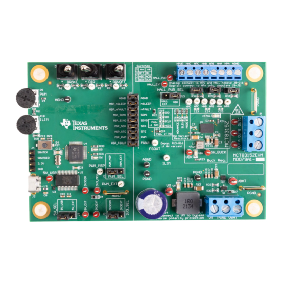
MCT8315Z
MCT8315ZEVM Printed Circuit Board (PCB - Top View)
Copyright © 2023 Texas Instruments Incorporated
3. Download the latest firmware for the
MCT8315ZEVM
on ti.com.
Features
•
GUI software with full configuration & control
capability.
•
MCU-to-MCx shunt jumper header with removable
shunts to disconnect main signals going to the
motor driver IC from the MCU.
– The shunts can be removed if the user wants to
control the MCT8315Z IC with an external MCU
or to use the EVM MCU to control an external
MCT8315Z IC.
Applications
•
Brushless-DC (BLDC) Motor modules
•
CPAP machines
•
Printers
•
Robotic vacuums
•
Small home appliances
•
Office automation machines
•
Factory automation and robotics
Description
MCT8315Z Evaluation Module
1
Advertisement
Table of Contents

Subscribe to Our Youtube Channel
Related Manuals for Texas Instruments MCT8315Z


Summary of Contents for Texas Instruments MCT8315Z
- Page 1 IC from the MCU. duty cycle for the PWM input of the MCT8315Z. The – The shunts can be removed if the user wants to MCU can also provide SPI communication for the SPI control the MCT8315Z IC with an external MCU variant of the MCT8315Z device.
-
Page 2: Kit Contents
MCT8315Z IC and EVM, confirm that the voltage and current specifications are not exceeded. 1.4 Device Information The MCT8315Z is a 4.5 V to 35 V, 4 A peak three-phase gate driver IC with sensored trapezoidal control for motor drive applications. The MCT8315Z provides three integrated half-bridges and a sensored trapezoidal control in a fixed-function state machine capable of directly driving a 3-phase brushless-DC motor without a microcontroller. - Page 3 Optionally, use the MCF8315Z GUI, refer to Section 3.1, to monitor the real-time speed of the motor, put the MCT8315Z into a low-power sleep mode, and read status of the EVMs LEDs. Figure 2-1. Reference for Quick Start Guide SNLU342 – DECEMBER 2023...
-
Page 4: Hardware Setup
4.5 V to 35 V and offers reverse-polarity protection and a Pi filter. The MCT8315ZEVM can support all variants of the MCT8315Z device with locations for Hardware resistors, SPI resistors, and buck components. Through the use of configurable shunts the MCT8315ZEVM can support many types of Hall sensor configurations. -
Page 5: Connection Details
5V_SEL jumper J3 and 3V3_SEL jumper J5 to connect external power rails. SNLU342 – DECEMBER 2023 MCT8315Z Evaluation Module Submit Document Feedback Copyright © 2023 Texas Instruments Incorporated... - Page 6 (PWM_MSP), and the duty cycle (ranging from 0–100%) is controlled by the potentiometer R5. The motor speed increases the more the potentiometer is turned counterclockwise, and decreases when turned clockwise. To select whether the PWM signal from the MSP or an external PWM is sourced to the MCT8315Z, use the PWM_SEL jumper J1.
-
Page 7: Led Lights
Designator Name Color Description Green Internal buck regulator is outputting nFAULT Lights up when fault condition has occurred on MCT8315Z Green Motor power is supplied to the board MSP_LED0 Used for UART or debugging MSP_LED1 Green Used for UART or debugging Figure 2-6. -
Page 8: User-Configurable Settings
Left Brake enabled Right Brake disabled Controls direction of motor Left Clockwise Counterclockwise Right DRVOFF Disables gate drivers Left MCT8315Z disabled Right MCT8315Z enabled MCT8315Z Evaluation Module SNLU342 – DECEMBER 2023 Submit Document Feedback Copyright © 2023 Texas Instruments Incorporated... - Page 9 MCT8315ZH or MCT8315ZT. R20–R22 resistors connect to AVDD and R26–R28 resistors connect to AGND. The default resistor divider configurations are in bold. SNLU342 – DECEMBER 2023 MCT8315Z Evaluation Module Submit Document Feedback Copyright © 2023 Texas Instruments Incorporated...
- Page 10 R20 and R26 R20 = R26 = DNP 15° electrical degrees) R20 = 100 kΩ 20° R20 = 22 kΩ 25° R20 = 0 Ω 30° MCT8315Z Evaluation Module SNLU342 – DECEMBER 2023 Submit Document Feedback Copyright © 2023 Texas Instruments Incorporated...
- Page 11 Resistor dividers in the Hardware Variant Resistors silkscreen box needs to be depopulated (R20-R22, R26-R28). This setup is shown in Figure 2-8. Figure 2-8. Resistors for MCT8315ZR (SPI variant) SNLU342 – DECEMBER 2023 MCT8315Z Evaluation Module Submit Document Feedback Copyright © 2023 Texas Instruments Incorporated...
- Page 12 Pulled low by the MCU to enable R16 = 0 Ω communication Table 2-5 show the status of populated and DNP resistors for the MCT8315Z variants. Table 2-5. Status of Resistors for MCT8315Z Variants HW Variant Resistors Device R13-R16 Status...
- Page 13 The MCT8315Z GUI is available on the dev.ti.com/gallery. The MCT8315Z GUI supports all variants of the MCT8315Z. The MCT8315Z GUI is able to measure the speed of the motor by monitoring the duty cycle of the 20-kHz PWM waveform and the frequency of the FGOUT output. Providing the number of poles the motor has to the GUI, the GUI calculates the speed of the motor in revolutions per minute (RPM).
-
Page 14: Running The Gui
3. The GUI launches a screen similar to the one shown in Figure 3-1. Figure 3-1. MCT8315Z GUI Alternatively, the MCT8315Z GUI can be downloaded and installed for offline use using the download feature in the TI Cloud Gallery. MCT8315Z Evaluation Module SNLU342 – DECEMBER 2023 Submit Document Feedback Copyright ©... - Page 15 Software Figure 3-2. MCT8315Z GUI Download Feature SNLU342 – DECEMBER 2023 MCT8315Z Evaluation Module Submit Document Feedback Copyright © 2023 Texas Instruments Incorporated...
- Page 16 4. In CCS, click on the Project tab and select Import CCS Projects. Click on Browse. Select the folder created in step 1 by extracting the MCT8315Z firmware. 5. Import the project into the workspace as shown in Figure 3-3.
- Page 17 (eZ-FET Debug Probe Side) (J101) MCT8315ZEVM 4-pin Spy-Bi-Wire Header (J4) 3.3V SBWTDIO SBWTDIO SBWTCK SBWTCK Figure 3-4. MSP430 LaunchPad ™ eZ-FET Probe Connected to MCT8315ZEVM SNLU342 – DECEMBER 2023 MCT8315Z Evaluation Module Submit Document Feedback Copyright © 2023 Texas Instruments Incorporated...
- Page 18 AGND nSCS/DIR SCS/DIR PGND AGND ILIM ILIM Thermal_Pad MCT8315Z0RRRYR PGND 41.2k 0.1uF AGND AGND AGND Figure 4-1. MCT8315Z 3-Phase Sensored Trapezoidal Motor Driver Schematic MCT8315Z Evaluation Module SNLU342 – DECEMBER 2023 Submit Document Feedback Copyright © 2023 Texas Instruments Incorporated...
- Page 19 Only populate one of these options: L1 - Inductor mode 47uH L2 - Inductor mode 22 uH (bottom) R10 - Resistor mode FB_BUCK Net-Tie Figure 4-3. Buck Regulator Schematic SNLU342 – DECEMBER 2023 MCT8315Z Evaluation Module Submit Document Feedback Copyright © 2023 Texas Instruments Incorporated...
- Page 20 MSP_nFAULT_P3.3 P3.3/OA2+ P6.5/TB3.6 P3.4/SMCLK P6.6/TB3CLK AGND AGND P3.5/OA3O P3.6/OA3- Populate jumpers to communicate onboard MSP430FR2355 to the MCT8315Z P3.7/OA3+ DVSS or depopulate jumpers to use standalone MSP430 or MCT8315Z. MSP430FR2355TPTR AGND Figure 4-4. MSP430FR2355 MCU FTDI REGULATOR Micro USB Connector...
- Page 21 Digital (single-ended): connect hall sensors to only HPx, install pullup jumpers J9-J11 Analog (differential): connect hall elements to HPx and HNx, remove pullup J9-J11 Figure 4-10. Connectors Schematic SNLU342 – DECEMBER 2023 MCT8315Z Evaluation Module Submit Document Feedback Copyright © 2023 Texas Instruments Incorporated...
-
Page 22: Pcb Layouts
Hardware Design Files www.ti.com 4.2 PCB Layouts Figure 4-11. EVM Board Dimensions MCT8315Z Evaluation Module SNLU342 – DECEMBER 2023 Submit Document Feedback Copyright © 2023 Texas Instruments Incorporated... - Page 23 Hardware Design Files Figure 4-12. EVM Top Overlay Figure 4-13. EVM Top Solder Mask SNLU342 – DECEMBER 2023 MCT8315Z Evaluation Module Submit Document Feedback Copyright © 2023 Texas Instruments Incorporated...
- Page 24 Hardware Design Files www.ti.com Figure 4-14. EVM Top Layer Figure 4-15. EVM Signal Layer 1 MCT8315Z Evaluation Module SNLU342 – DECEMBER 2023 Submit Document Feedback Copyright © 2023 Texas Instruments Incorporated...
- Page 25 Hardware Design Files Figure 4-16. EVM Signal Layer 2 Figure 4-17. EVM Bottom Layer SNLU342 – DECEMBER 2023 MCT8315Z Evaluation Module Submit Document Feedback Copyright © 2023 Texas Instruments Incorporated...
- Page 26 Hardware Design Files www.ti.com Figure 4-18. EVM Bottom Solder Mask Figure 4-19. EVM Bottom Overlay MCT8315Z Evaluation Module SNLU342 – DECEMBER 2023 Submit Document Feedback Copyright © 2023 Texas Instruments Incorporated...
- Page 27 Diode, Schottky, 40 V, 0.75 A, AEC-Q101, 40 V SOD-323 BAT165E6327HTSA1 Infineon Technologies SOD-323 LED, Red, SMD Red LED, 1.6x0.8x0.8mm LTST-C190KRKT Lite-On Green LED, Green, SMD 1.6x0.8x0.8mm LTST-C190GKT Lite-On SNLU342 – DECEMBER 2023 MCT8315Z Evaluation Module Submit Document Feedback Copyright © 2023 Texas Instruments Incorporated...
- Page 28 Nexperia Mount DFN2020MD-6 R1, R2, R3, R6, R7, R8, R32, R33, R34, 10.0k RES, 10.0 k, 1%, 0.1 W, 0603 RC0603FR-0710KL Yageo R35, R36 MCT8315Z Evaluation Module SNLU342 – DECEMBER 2023 Submit Document Feedback Copyright © 2023 Texas Instruments Incorporated...
- Page 29 TP29, TP30, TP31 TP6, TP7, TP8, TP9, TP10, TP13, TP14, Test Point, Miniature, Red, TH Red Miniature Testpoint 5000 Keystone Electronics TP23, TP27, TP32, TP33, TP34 SNLU342 – DECEMBER 2023 MCT8315Z Evaluation Module Submit Document Feedback Copyright © 2023 Texas Instruments Incorporated...
- Page 30 16-Bit 24 MHz 32 KB (32K x 8) FRAM 48- LQFP48 MSP430FR2355TPTR Texas Instruments LQFP (7x7) Resonator, 4 MHz, 39 pF, AEC-Q200 Grade 1, 4.5x1.2x2 mm CSTCR4M00G55B-R0 MuRata MCT8315Z Evaluation Module SNLU342 – DECEMBER 2023 Submit Document Feedback Copyright © 2023 Texas Instruments Incorporated...
- Page 31 Google LLC. Firefox ® is a registered trademark of Mozilla Foundation. All trademarks are the property of their respective owners. SNLU342 – DECEMBER 2023 MCT8315Z Evaluation Module Submit Document Feedback Copyright © 2023 Texas Instruments Incorporated...
- Page 32 TI products. TI’s provision of these resources does not expand or otherwise alter TI’s applicable warranties or warranty disclaimers for TI products. TI objects to and rejects any additional or different terms you may have proposed. IMPORTANT NOTICE Mailing Address: Texas Instruments, Post Office Box 655303, Dallas, Texas 75265 Copyright © 2023, Texas Instruments Incorporated...
Need help?
Do you have a question about the MCT8315Z and is the answer not in the manual?
Questions and answers