Table of Contents
Advertisement
Quick Links
www.ti.com
EVM User's Guide: MCT8314ZEVM
MCT8314Z Evaluation Module
Description
The MCT8314ZEVM allows users to evaluate the
performance of the MCT8314Z motor driver. The
EVM includes an onboard FTDI chip to convert
USB communication from the micro-USB connector
into UART. An onboard MSP430FR2355 MCU
translates the UART communication and onboard
potentiometers into control signals and a variable
duty cycle for the PWM input of the MCT8314Z. The
MCU can also provide SPI communication for the SPI
variant of the MCT8314Z device. There are many
user-selectable jumpers, resistors, connectors, and
test points to assist with evaluating the many features
of the MCT8314Z device and the configurable device-
specific settings.
SNLU341 – DECEMBER 2023
Submit Document Feedback
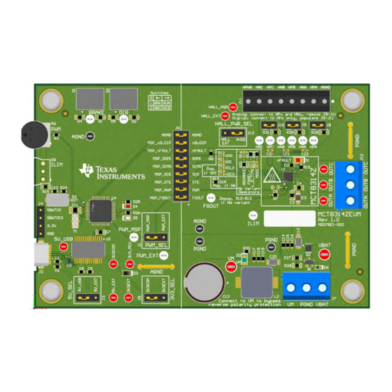
MCT8314ZEVM Printed Circuit Board (PCB - Top View)
Copyright © 2023 Texas Instruments Incorporated
Get Started
1. Order the MCT8314ZEVM on ti.com.
2. Visit
dev.ti.com/gallery
software or access the web hosted GUI software.
3. Download the latest firmware for the
MCT8314ZEVM
on ti.com.
Features
•
GUI software with full configuration & control
capability.
•
MCU-to-MCx shunt jumper header with removable
shunts to disconnect main signals going to the
motor driver IC from the MCU. The shunts can
be removed if the user desires to control the
MCT8314Z IC with an external MCU or to use the
EVM MCU to control an external MCT8314Z IC.
Applications
•
Vacuum robots
•
Motorized blinds
•
IP cameras
Description
to download the GUI
MCT8314Z Evaluation Module
1
Advertisement
Table of Contents

Related Manuals for Texas Instruments MCT8314Z


Summary of Contents for Texas Instruments MCT8314Z
- Page 1 UART communication and onboard Features potentiometers into control signals and a variable duty cycle for the PWM input of the MCT8314Z. The • GUI software with full configuration & control MCU can also provide SPI communication for the SPI capability.
-
Page 2: Kit Contents
MCT8314Z IC and EVM, confirm that the voltage and current specifications are not exceeded. 1.4 Device Information The MCT8314Z is a 4.5 V to 35 V, 1.5 A peak three-phase gate driver IC with sensored trapezoidal control for motor drive applications. The MCT8314Z provides three integrated half-bridges and a sensored trapezoidal control in a fixed-function state machine capable of directly driving a 3-phase brushless-DC motor without a microcontroller. - Page 3 Optionally, use the MCF8314Z GUI, refer to Section 3.1, to monitor the real-time speed of the motor, put the MCT8314Z into a low-power sleep mode, and read status of the EVMs LEDs. Figure 2-1. Reference for Quick Start Guide SNLU341 – DECEMBER 2023...
-
Page 4: Hardware Setup
4.5 V to 35 V and offers reverse-polarity protection and a Pi filter. The MCT8314ZEVM can support all variants of the MCT8314Z device with locations for Hardware resistors and SPI resistors. Through the use of configurable shunts the MCT8314ZEVM can support many types of Hall sensor configurations. For interfacing with the MCT8314Z GUI the MCT8314ZEVM has a FTDI chip to support USB-to-UART and a MSP430. -
Page 5: Connection Details
Hall sensor, connect to only the HPx pins for each phase and populate jumpers J8-J10. Figure 2-3. Connections from Motor to MCT8314ZEVM SNLU341 – DECEMBER 2023 MCT8314Z Evaluation Module Submit Document Feedback Copyright © 2023 Texas Instruments Incorporated... - Page 6 5V_SEL jumper J3 and 3V3_SEL jumper J5 to connect external power rails. Figure 2-4. Micro-USB Connector and UART for MCT8314ZEVM MCT8314Z Evaluation Module SNLU341 – DECEMBER 2023 Submit Document Feedback Copyright © 2023 Texas Instruments Incorporated...
- Page 7 (PWM_MSP), and the duty cycle (ranging from 0–100%) is controlled by the potentiometer R6. The motor speed increases the more the potentiometer is turned counterclockwise, and decreases when turned clockwise. To select whether the PWM signal from the MSP or an external PWM is sourced to the MCT8314Z, use the PWM_SEL jumper J1.
-
Page 8: Led Lights
Table 2-1. Description of MCT8314ZEVM LEDs (Default in Bold After Power Up) Designator Name Color Description nFAULT Lights up when fault condition has occurred on MCT8314Z. Green Motor power is supplied to the board. MSP_LED0 Used for UART or debugging. MSP_LED1 Green Used for UART or debugging. -
Page 9: User-Configurable Settings
ILIM = 1.25 V = 1.45 A ILIM current limit can be calculated 6.2 kΩ limit using the equation 9000 / R15 = cycle-by-cycle current limit. SNLU341 – DECEMBER 2023 MCT8314Z Evaluation Module Submit Document Feedback Copyright © 2023 Texas Instruments Incorporated... - Page 10 MCT8314ZH. R16–R18 resistors connect to AVDD and R21–R23 resistors connect to AGND. The default resistor divider configurations are in bold. MCT8314Z Evaluation Module SNLU341 – DECEMBER 2023 Submit Document Feedback Copyright © 2023 Texas Instruments Incorporated...
- Page 11 R16 = R21 = DNP 15° value (in electrical R16 = 100 kΩ 20° degrees) R16 = 22 kΩ 25° R16 = 0 Ω 30° SNLU341 – DECEMBER 2023 MCT8314Z Evaluation Module Submit Document Feedback Copyright © 2023 Texas Instruments Incorporated...
- Page 12 Resistor dividers in the Hardware Variant Resistors silk screen box needs be depopulated (R16-R18, R21- R23). This setup is shown in Figure 2-8. Figure 2-8. Resistors for MCT8314ZS (SPI variant) MCT8314Z Evaluation Module SNLU341 – DECEMBER 2023 Submit Document Feedback Copyright © 2023 Texas Instruments Incorporated...
- Page 13 Pulled low by the MCU to enable R16 = 0 Ω communication Table 2-5 show the status of populated and DNP resistors for the MCT834Z variants. Table 2-5. Status of Resistors for MCT8314Z Variants Device R13-R16 status R17 status HW variant resistors status...
- Page 14 By default, the MSP430 already contains the firmware required for the EVM to be able to connect and communicate with the MCT8314Z GUI. If there is a FW update or the GUI does not connect to the EVM then the user must flash the code onto the MSP430.
-
Page 15: Running The Gui
3. Once the GUI has launched a screen similar to the one shown in Figure 3-1 appears. Figure 3-1. MCT8314Z GUI Alternatively the MCT8314Z GUI can be downloaded and intalled for offline use using the download feature in the TI Cloud Gallery. SNLU341 – DECEMBER 2023 MCT8314Z Evaluation Module Submit Document Feedback Copyright ©... - Page 16 Software www.ti.com Figure 3-2. MCT8314Z GUI Download Feature MCT8314Z Evaluation Module SNLU341 – DECEMBER 2023 Submit Document Feedback Copyright © 2023 Texas Instruments Incorporated...
- Page 17 4. In CCS, click on the Project tab and select Import CCS Projects. Click on Browse. 5. Select the folder created in step 1 by extracting the MCT8314Z firmware. 6. Import the project into the workspace as shown in Figure 3-3.
- Page 18 MSP430 LaunchPad (eZ-FET Debug Probe Side) (J101) MCT8314ZEVM 4-pin Spy-Bi-Wire Header (J4) 3.3V SBWTDIO SBWTDIO SBWTCK SBWTCK Figure 3-4. MSP430 LaunchPad eZ-FET Probe Connected to MCT8314ZEVM MCT8314Z Evaluation Module SNLU341 – DECEMBER 2023 Submit Document Feedback Copyright © 2023 Texas Instruments Incorporated...
- Page 19 Figure 4-1 through Figure 4-9 illustrate the EVM schematics. 4.1.1 MCT8314Z 3-Phase Sensored Trapezoidal Motor Driver Figure 4-1. MCT8314Z 3-Phase Sensored Trapezoidal Motor Driver 4.1.2 Power Supplies Figure 4-2. Main Supply SNLU341 – DECEMBER 2023 MCT8314Z Evaluation Module Submit Document Feedback...
- Page 20 Hardware Design Files www.ti.com 4.1.3 MCU Interface Figure 4-3. MSP430FR2355 MCU Figure 4-4. USB to UART Schematic MCT8314Z Evaluation Module SNLU341 – DECEMBER 2023 Submit Document Feedback Copyright © 2023 Texas Instruments Incorporated...
-
Page 21: User Interface
Hardware Design Files Figure 4-5. MCU Programming and Debug Schematic 4.1.4 User Interface Figure 4-6. Status LEDs Schematic Figure 4-7. Hardware Variant Resistors Schematic SNLU341 – DECEMBER 2023 MCT8314Z Evaluation Module Submit Document Feedback Copyright © 2023 Texas Instruments Incorporated... - Page 22 Hardware Design Files www.ti.com Figure 4-8. Switches and Speed Input Schematic Figure 4-9. Connectors Schematic MCT8314Z Evaluation Module SNLU341 – DECEMBER 2023 Submit Document Feedback Copyright © 2023 Texas Instruments Incorporated...
-
Page 23: Pcb Layouts
Hardware Design Files 4.2 PCB Layouts Figure 4-10. EVM Board Dimensions Figure 4-11. EVM Top Overlay SNLU341 – DECEMBER 2023 MCT8314Z Evaluation Module Submit Document Feedback Copyright © 2023 Texas Instruments Incorporated... - Page 24 Hardware Design Files www.ti.com Figure 4-12. EVM Top Solder Mask Figure 4-13. EVM Top Layer MCT8314Z Evaluation Module SNLU341 – DECEMBER 2023 Submit Document Feedback Copyright © 2023 Texas Instruments Incorporated...
- Page 25 Hardware Design Files Figure 4-14. EVM Signal Layer 1 Figure 4-15. EVM Signal Layer 2 SNLU341 – DECEMBER 2023 MCT8314Z Evaluation Module Submit Document Feedback Copyright © 2023 Texas Instruments Incorporated...
- Page 26 Hardware Design Files www.ti.com Figure 4-16. EVM Bottom Layer Figure 4-17. EVM Bottom Solder Mask MCT8314Z Evaluation Module SNLU341 – DECEMBER 2023 Submit Document Feedback Copyright © 2023 Texas Instruments Incorporated...
- Page 27 Hardware Design Files Figure 4-18. EVM Bottom Overlay SNLU341 – DECEMBER 2023 MCT8314Z Evaluation Module Submit Document Feedback Copyright © 2023 Texas Instruments Incorporated...
- Page 28 100 V Diode, Switching, 100 V, 0.25 A, SOD-523 SOD-523 BAS516,115 Nexperia Fiducial mark. There is nothing to buy or FID1, FID2, FID3 mount. MCT8314Z Evaluation Module SNLU341 – DECEMBER 2023 Submit Document Feedback Copyright © 2023 Texas Instruments Incorporated...
- Page 29 3352T-1-253LF Bourns R7, R8 5.1k RES, 5.1 k, 5%, 0.1 W, 0603 RC0603JR-075K1L Yageo 6.2k RES, 6.2 k, 5%, 0.1 W, 0603 RC0603JR-076K2L Yageo SNLU341 – DECEMBER 2023 MCT8314Z Evaluation Module Submit Document Feedback Copyright © 2023 Texas Instruments Incorporated...
- Page 30 Texas Instruments USB to Serial UART, SSOP28 SSOP28 FT232RL FTDI 4-Channel ESD Protection Array for High- DRY0006A TPD4E004DRYR Texas Instruments Speed Data Interfaces, DRY0006A (USON-6) MCT8314Z Evaluation Module SNLU341 – DECEMBER 2023 Submit Document Feedback Copyright © 2023 Texas Instruments Incorporated...
- Page 31 RES, 0, 5%, 0.1 W, AEC-Q200 Grade 0, 0603 ERJ-3GEY0R00V Panasonic RES, 100 k, 0.1%, 0.1 W, AEC-Q200 Grade 0, R16, R23 100k ERA-3AEB104V Panasonic 0603 SNLU341 – DECEMBER 2023 MCT8314Z Evaluation Module Submit Document Feedback Copyright © 2023 Texas Instruments Incorporated...
- Page 32 Google LLC. Firefox ® is a registered trademark of Mozilla Foundation. All trademarks are the property of their respective owners. MCT8314Z Evaluation Module SNLU341 – DECEMBER 2023 Submit Document Feedback Copyright © 2023 Texas Instruments Incorporated...
- Page 33 STANDARD TERMS FOR EVALUATION MODULES Delivery: TI delivers TI evaluation boards, kits, or modules, including any accompanying demonstration software, components, and/or documentation which may be provided together or separately (collectively, an “EVM” or “EVMs”) to the User (“User”) in accordance with the terms set forth herein.
- Page 34 www.ti.com Regulatory Notices: 3.1 United States 3.1.1 Notice applicable to EVMs not FCC-Approved: FCC NOTICE: This kit is designed to allow product developers to evaluate electronic components, circuitry, or software associated with the kit to determine whether to incorporate such items in a finished product and software developers to write software applications for use with the end product.
- Page 35 www.ti.com Concernant les EVMs avec antennes détachables Conformément à la réglementation d'Industrie Canada, le présent émetteur radio peut fonctionner avec une antenne d'un type et d'un gain maximal (ou inférieur) approuvé pour l'émetteur par Industrie Canada. Dans le but de réduire les risques de brouillage radioélectrique à...
- Page 36 www.ti.com EVM Use Restrictions and Warnings: 4.1 EVMS ARE NOT FOR USE IN FUNCTIONAL SAFETY AND/OR SAFETY CRITICAL EVALUATIONS, INCLUDING BUT NOT LIMITED TO EVALUATIONS OF LIFE SUPPORT APPLICATIONS. 4.2 User must read and apply the user guide and other available documentation provided by TI regarding the EVM prior to handling or using the EVM, including without limitation any warning or restriction notices.
- Page 37 Notwithstanding the foregoing, any judgment may be enforced in any United States or foreign court, and TI may seek injunctive relief in any United States or foreign court. Mailing Address: Texas Instruments, Post Office Box 655303, Dallas, Texas 75265 Copyright © 2023, Texas Instruments Incorporated...
-
Page 38: Important Notice
TI products. TI’s provision of these resources does not expand or otherwise alter TI’s applicable warranties or warranty disclaimers for TI products. TI objects to and rejects any additional or different terms you may have proposed. IMPORTANT NOTICE Mailing Address: Texas Instruments, Post Office Box 655303, Dallas, Texas 75265 Copyright © 2023, Texas Instruments Incorporated...
Need help?
Do you have a question about the MCT8314Z and is the answer not in the manual?
Questions and answers