Table of Contents
Advertisement
Quick Links
www.ti.com
User's Guide
MCF8315EVM Evaluation Module
This document is provided with the MCF8315 customer evaluation module (EVM) as a supplement to the
MCF8315 data sheet
(MCF8315A Three-Phase Sensorless-FOC BLDC Motor
the hardware implementation of the EVM and how to setup and power the board.
Warnings..........................................................................................................................................................2
2
Introduction.............................................................................................................................................................................3
Guide....................................................................................................................................................................4
4.1 Hardware Connections Overview - MCF8315EVM...........................................................................................................
4.2 Connection Details.............................................................................................................................................................
4.3 MSP430FR2355 Microcontroller & User Interface.............................................................................................................
Lights..........................................................................................................................................................................8
4.5 User-Configurable Settings................................................................................................................................................
Setup.....................................................................................................................................................................11
6 MCF8315 GUI Application....................................................................................................................................................
6.1 Running the GUI..............................................................................................................................................................
6.2 Offline Installer.................................................................................................................................................................
7 MSP430FR2355 Interface Firmware....................................................................................................................................
7.2 Using the eZ-FET to Program the MSP430FR2355........................................................................................................
8
Schematics............................................................................................................................................................................16
8.1 Main Supply and Pi Filter.................................................................................................................................................
Interface.................................................................................................................................................16
8.3 USB to UART...................................................................................................................................................................
8.5 MSP430FR2355 MCU.....................................................................................................................................................
Regulator.................................................................................................................................................................19
8.8 Status LEDs.....................................................................................................................................................................
8.9 Switches and Speed Input...............................................................................................................................................
9 Revision History...................................................................................................................................................................
Trademarks
LaunchPad
™
is a trademark of Texas Instruments.
All trademarks are the property of their respective owners.
SLLU362 - DECEMBER 2022
Submit Document Feedback
Table of Contents
Overview.........................................................................................................................................5
Debug........................................................................................................................................17
Driver....................................................................................................18
Copyright © 2022 Texas Instruments Incorporated
ABSTRACT
Table of Contents
Driver). This User's Guide details
Code...................................14
MCF8315EVM Evaluation Module
5
5
7
9
12
12
12
14
14
16
17
18
20
20
20
1
Advertisement
Table of Contents

Related Manuals for Texas Instruments MCF8315EVM


Summary of Contents for Texas Instruments MCF8315EVM
-
Page 1: Table Of Contents
Table of Contents 1 Cautions and Warnings................................2 Introduction.....................................3 3 Quick Start Guide..................................4 4 Hardware and Software Overview............................5 4.1 Hardware Connections Overview – MCF8315EVM......................4.2 Connection Details................................4.3 MSP430FR2355 Microcontroller & User Interface......................4.4 LED Lights..................................8 4.5 User-Configurable Settings..............................5 Hardware Setup..................................11 6 MCF8315 GUI Application.............................. -
Page 2: Cautions And Warnings
Observe the following cautions and warnings as printed on the EVM board. HOT SURFACE: Caution Hot Surface! Contact may cause burns. Do not touch. Please take the proper precautions when operating. MCF8315EVM Evaluation Module SLLU362 – DECEMBER 2022 Submit Document Feedback Copyright © 2022 Texas Instruments Incorporated... -
Page 3: Introduction
This document serves as a startup guide to supplement the MCF8315EVM. It is intended for engineers to design, implement, and validate reference hardware for the MCF8315 device. -
Page 4: Quick Start Guide
3 Quick Start Guide The MCF8315EVM requires a power supply source, which has a recommended operating range from a 4.5-V to 35-V. To setup and power the EVM, follow the sequence below: 1. Connect motor phases to A, B, C on connector J8. -
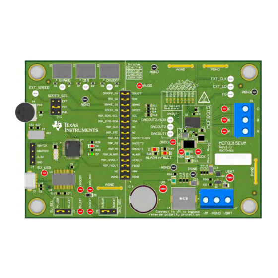
Page 5: Hardware And Software Overview
4.2 Connection Details Figure 4-2 shows the connections made to the MCF8315EVM in order to spin a 3-phase sensorless Brushless- DC motor. An 4.5-V to 35-V power supply or battery is connected to the VBAT or VM and PGND terminals on connector J7. - Page 6 Figure 4-2. Connections from Motor to MCF8315EVM Figure 4-3 shows where the micro-USB cable is plugged into the MCF8315EVM to provide communication between evaluation module and GUI. The USB data and 5 V power from the USB is converted into UART data and 3.3 V power to power the MSP430FR2355 microcontroller.
-
Page 7: Msp430Fr2355 Microcontroller & User Interface
Finally, a shunt jumper bridge on the 32-pin connector J6 ties all signals between the microcontroller and MCF8315. These jumpers can be inserted or removed as needed in order to isolate the microcontroller from the gate driver. This allows for microcontroller signal debugging or using the MCF8315EVM as a standalone gate driver with an external microcontroller. -
Page 8: Led Lights
4.4 LED Lights The MCF8315EVM has 6 status LEDs implemented that provide the status of power supplies and functionalities of the evaluation module. By default, the VM LED and 3.3 V Buck LEDs will light up when the board is powered and the program has been flashed onto the microcontroller. -
Page 9: User-Configurable Settings
Hardware and Software Overview Figure 4-5. MCF8315EVM LEDs 4.5 User-Configurable Settings The MCF8315EVM includes a variety of user-selectable jumpers, switches, and resistors on the entirety of the evaluation board to configure settings. Table 4-2 summarizes all of these configurable settings. - Page 10 Hardware and Software Overview www.ti.com Table 4-2. Description of User-Selectable Settings on MCF8315EVM (Default in Bold) (continued) Designator Setting Name Description Layer Position Function SPEED_SEL Selects SPEED input source J1 = EXT External EXT_SPEED test point J1 = POT From...
-
Page 11: Hardware Setup
Hardware Setup 5 Hardware Setup The hardware required to run the motor is the MCF8315EVM, a Micro-USB cable, and a power supply with a DC output from 4.5-V to 35-V. Follow these steps to start up the MCF8315EVM: 1. Connect the DC power supply to header J7. Connect to VBAT and PGND to apply reverse polarity protection and the pi filter to the EVM. -
Page 12: Mcf8315 Gui Application
6 MCF8315 GUI Application The MCF8315EVM includes a USB-UART interface, using a MSP430FR2355 microcontroller, that serves as a communication bridge between a host PC and the MCF8315 device for configuring various device settings and reading fault diagnostic information. A MCF8315A GUI is available to interface with and configure the MCF8315 using this communication interface. - Page 13 MCF8315 GUI Application Figure 6-2. MCF8315A GUI Offline Installer SLLU362 – DECEMBER 2022 MCF8315EVM Evaluation Module Submit Document Feedback Copyright © 2022 Texas Instruments Incorporated...
-
Page 14: Msp430Fr2355 Interface Firmware
MSP-EXP430FR2355 LaunchPad Development Kit to provide the debug probe. Follow the steps below to download the code for the MCF8315EVM to use with the GUI. 7.1 Downloading Code Composer Studio and Importing MSP430FR2355 Interface Firmware Code 1. - Page 15 6. Stop the debug session, close Code Composer Studio, disconnect the SPI-by-Wire jumpers, and unplug the micro-USB cable from the MSP430 LaunchPad. Table 7-1. SPY-BI-Wire Connections Needed to Program MSP430FR2355 ™ MSP430 LaunchPad (eZ-FET Debug Probe Side) (J101) MCF8315EVM 4-pin SPI-by-Wire Header (J4) 3.3V SBWTDIO SBWTDIO SBWTCK SBWTCK ™...
-
Page 16: Schematics
8.1 Main Supply and Pi Filter Figure 8-1. Main Supply and Pi Filter Schematic 8.2 Connectors and Interface Figure 8-2. Connectors and Interface Schematic MCF8315EVM Evaluation Module SLLU362 – DECEMBER 2022 Submit Document Feedback Copyright © 2022 Texas Instruments Incorporated... -
Page 17: Usb To Uart
Schematics 8.3 USB to UART Figure 8-3. USB to UART Schematic 8.4 MCU Programming and Debug Figure 8-4. MCU Programming and Debug Schematic SLLU362 – DECEMBER 2022 MCF8315EVM Evaluation Module Submit Document Feedback Copyright © 2022 Texas Instruments Incorporated... -
Page 18: Msp430Fr2355 Mcu
8.5 MSP430FR2355 MCU Figure 8-5. MSP430FR2355 MCU Schematic 8.6 MCF8315 3-Phase Sensorless FOC Integrated Driver Figure 8-6. MCF8315 3-Phase Sensorless FOC Integrated Driver Schematic MCF8315EVM Evaluation Module SLLU362 – DECEMBER 2022 Submit Document Feedback Copyright © 2022 Texas Instruments Incorporated... -
Page 19: Buck Regulator
Schematics 8.7 Buck Regulator Figure 8-7. Buck Regulator Schematic SLLU362 – DECEMBER 2022 MCF8315EVM Evaluation Module Submit Document Feedback Copyright © 2022 Texas Instruments Incorporated... -
Page 20: Status Leds
9 Revision History NOTE: Page numbers for previous revisions may differ from page numbers in the current version. DATE REVISION NOTES December 2022 Initial Release MCF8315EVM Evaluation Module SLLU362 – DECEMBER 2022 Submit Document Feedback Copyright © 2022 Texas Instruments Incorporated... - Page 21 STANDARD TERMS FOR EVALUATION MODULES Delivery: TI delivers TI evaluation boards, kits, or modules, including any accompanying demonstration software, components, and/or documentation which may be provided together or separately (collectively, an “EVM” or “EVMs”) to the User (“User”) in accordance with the terms set forth herein.
- Page 22 www.ti.com Regulatory Notices: 3.1 United States 3.1.1 Notice applicable to EVMs not FCC-Approved: FCC NOTICE: This kit is designed to allow product developers to evaluate electronic components, circuitry, or software associated with the kit to determine whether to incorporate such items in a finished product and software developers to write software applications for use with the end product.
- Page 23 www.ti.com Concernant les EVMs avec antennes détachables Conformément à la réglementation d'Industrie Canada, le présent émetteur radio peut fonctionner avec une antenne d'un type et d'un gain maximal (ou inférieur) approuvé pour l'émetteur par Industrie Canada. Dans le but de réduire les risques de brouillage radioélectrique à...
- Page 24 www.ti.com EVM Use Restrictions and Warnings: 4.1 EVMS ARE NOT FOR USE IN FUNCTIONAL SAFETY AND/OR SAFETY CRITICAL EVALUATIONS, INCLUDING BUT NOT LIMITED TO EVALUATIONS OF LIFE SUPPORT APPLICATIONS. 4.2 User must read and apply the user guide and other available documentation provided by TI regarding the EVM prior to handling or using the EVM, including without limitation any warning or restriction notices.
- Page 25 Notwithstanding the foregoing, any judgment may be enforced in any United States or foreign court, and TI may seek injunctive relief in any United States or foreign court. Mailing Address: Texas Instruments, Post Office Box 655303, Dallas, Texas 75265 Copyright © 2019, Texas Instruments Incorporated...
- Page 26 TI products. TI’s provision of these resources does not expand or otherwise alter TI’s applicable warranties or warranty disclaimers for TI products. TI objects to and rejects any additional or different terms you may have proposed. IMPORTANT NOTICE Mailing Address: Texas Instruments, Post Office Box 655303, Dallas, Texas 75265 Copyright © 2022, Texas Instruments Incorporated...
Need help?
Do you have a question about the MCF8315EVM and is the answer not in the manual?
Questions and answers