Advertisement
Quick Links
The MMWCAS-DSP-EVM is an evaluation platform utilizing the TDA2x high performance, multimedia
application processor based on enhance OMAP architecture implemented with 28-nm technology. The
MMWCAS-RF-EVM is a 4-device, cascaded, array of AWR1243P mmWave devices. This user guide
references the MMWCAS-RF-EVM and Radar Board as the same items. Both boards together provide a
full Radar system evaluation.
...................................................................................................................
1
Introduction
2
Hardware Specifications
3
mmWave Studio and Matlab Post Processing
1
Caution Hot Surface Warning located on EVM
2
MMWCAS-DSP-EVM Functional Block Diagram
3
MMWCAS-DSP-EVM - Front
4
MMWCAS-DSP-EVM – Back
5
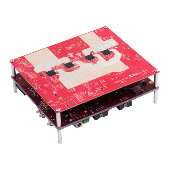
MMWCAS-DSP-EVM (bottom) and MMWCAS-RF-EVM (top) Board Alignment
6
System Power Distribution Network
7
DSP Host to RF Board Connector #1 (J1)
8
DSP Host to RF Board Connector #2 (J18)
9
FPGA Flash Programming Header Pinout
1
DSP Host to RF Board Connector Pin Table (J1)
2
DSP Host to RF Board Connector Pin Table (J18)
3
USB Connector Pin Table (J16)
4
GPIO List and Description
5
User Configurable Supported Boot Modes
6
Push Button Functionality Information
7
User and Status LED Reference Designator and Description
Trademarks
MicroSD is a trademark of SD-3C, LLC.
All other trademarks are the property of their respective owners.
SPRUIS6 – September 2019
Submit Documentation Feedback
Contents
....................................................................................................
.........................................................................
List of Figures
.........................................................................
.......................................................................
..............................................................................................
.............................................................................................
......................................................................................
..............................................................................
...........................................................................
.............................................................................
List of Tables
......................................................................
...................................................................
.........................................................................................
................................................................................................
.............................................................................
..................................................................................
Copyright © 2019, Texas Instruments Incorporated
SPRUIS6 – September 2019
MMWCAS-DSP-EVM
...................................
.......................................................
MMWCAS-DSP-EVM
User's Guide
2
3
19
3
4
5
6
7
8
9
12
16
9
12
15
17
18
18
18
1
Advertisement

Subscribe to Our Youtube Channel
Related Manuals for Texas Instruments MMWCAS-DSP-EVM


Summary of Contents for Texas Instruments MMWCAS-DSP-EVM
- Page 1 SPRUIS6 – September 2019 MMWCAS-DSP-EVM The MMWCAS-DSP-EVM is an evaluation platform utilizing the TDA2x high performance, multimedia application processor based on enhance OMAP architecture implemented with 28-nm technology. The MMWCAS-RF-EVM is a 4-device, cascaded, array of AWR1243P mmWave devices. This user guide references the MMWCAS-RF-EVM and Radar Board as the same items.
-
Page 2: Key Features
Introduction www.ti.com Introduction The MMWCAS-DSP-EVM is an evaluation platform utilizing the TDA2x high performance, multimedia application processor based on enhance OMAP architecture implemented with 28-nm technology. The MMWCAS-DSP-EVM provides a processing foundation for a cascaded imaging radar system. Cascade radar devices can support front, long-range(LRR) beam-forming applications as well as corner and side-cascade radar and sensor fusion platforms. -
Page 3: Kit Contents
Introduction www.ti.com Kit Contents The following items are included with the MMWCAS-DSP-EVM kit. Unbox the board and identify various components and connectors as detailed in the user guide. • MMWCAS-DSP-EVM Board • 512GB NVMe PCIE m.2 2280 SSD(assembled on EVM) •... - Page 4 1:4 MUX UART AWR#3 HDMI Type-A HDMI1.4a UART AWR#4 Connector SPI1 SPI AWR#1/4 SPI3 SPI AWR#2/3 GPIO ERROR GPIO AWR_RESETS Figure 2. MMWCAS-DSP-EVM Functional Block Diagram MMWCAS-DSP-EVM SPRUIS6 – September 2019 Submit Documentation Feedback Copyright © 2019, Texas Instruments Incorporated...
- Page 5 Hardware Specifications www.ti.com Board Dimensions & Description The MMWCAS-DSP-EVM dimensions are 160 mm × 136 mm. It is a 22-layer board fabricated with epoxy fiberglass (UL94V-0 Certified). Figure 3 Figure 4 show the top and bottom layers with key components identified.
- Page 6 Cascade RF board connector PCIe m.2 SSD connector and screw hole Cascade RF board connector MicroSD Cascade RF board connector MicroSD Recepticle Recepticle Figure 4. MMWCAS-DSP-EVM – Back MMWCAS-DSP-EVM SPRUIS6 – September 2019 Submit Documentation Feedback Copyright © 2019, Texas Instruments Incorporated...
- Page 7 Attaching MMWCAS-DSP-EVM to MMWCAS-RF-EVM The MMWCAS-DSP-EVM is designed to have a companion RF board attached to capture radar data. The EVM provides 5-V power and necessary control to the RF board upon connecting. The boards align and attach through the board to board connectors (J1 and J18) on the EVM. The connectors are keyed to prevent incorrect, 180 degree, opposite orientation.
- Page 8 J1 contains all the reset, boot, digital control, and CSI2.0 data paths for AWR1243P #1 and AWR1243P #2. J18 contains the same but for AWR1243P #3 and AWR1243P #4. Both connectors share common 5-V and GND return paths. MMWCAS-DSP-EVM SPRUIS6 – September 2019 Submit Documentation Feedback Copyright © 2019, Texas Instruments Incorporated...
- Page 9 System ground return AWR1_CLK_P Input AWR #1 CSI2 Clock AWR1_CLK_N Input AWR #1 CSI2 Clock Power System ground return Passive Test point Power System ground return SPRUIS6 – September 2019 MMWCAS-DSP-EVM Submit Documentation Feedback Copyright © 2019, Texas Instruments Incorporated...
- Page 10 System ground return SPI1_MISO Input AWR#1 SPI Slave MISO AWR1_SPI_INT Input AWR#1 SPI Slave Interrupt AWR1_CS0n Output AWR#1 SPI Slave CS0N SPI1_MOSI Output AWR#1 SPI Slave MOSI MMWCAS-DSP-EVM SPRUIS6 – September 2019 Submit Documentation Feedback Copyright © 2019, Texas Instruments Incorporated...
- Page 11 Output AWR#2 WARM_RESET signal Power System ground return AWR_SOP_PMICCLKOUT Output AWR#2 PMICCLKOUT/SOP2 AWR_SOP_SYNCOUT Output AWR#2 SYNCOUT/SOP1 signal AWR_SOP_TDO Output AWR#2 TDO/SOP0 signal Power System ground return SPRUIS6 – September 2019 MMWCAS-DSP-EVM Submit Documentation Feedback Copyright © 2019, Texas Instruments Incorporated...
- Page 12 Host Board Connector 1(J18) - Mated to RF Board P2 Pin Number Net Name Pin Type Function/Description CONN2_MON Passive Connection Monitor Passive Passive Passive Passive Power System ground return MMWCAS-DSP-EVM SPRUIS6 – September 2019 Submit Documentation Feedback Copyright © 2019, Texas Instruments Incorporated...
- Page 13 E_PMIC_SDA - Primary LP87524-Q1 PMIC I2C I2C5_SCL Output E_PMIC_SCL - Primary LP87524-Q1 PMIC I2C Power System ground return SPI3_SCLK Output AWR#3 SPI Slave SCLK SPI3_MOSI Output AWR#3 SPI Slave MOSI SPRUIS6 – September 2019 MMWCAS-DSP-EVM Submit Documentation Feedback Copyright © 2019, Texas Instruments Incorporated...
- Page 14 AWR #3 CSI2 TX0 Power System ground return AWR3_D1_N Input AWR #3 CSI2 TX1 AWR3_D1_P Input AWR #3 CSI2 TX1 Power System ground return Power System ground return MMWCAS-DSP-EVM SPRUIS6 – September 2019 Submit Documentation Feedback Copyright © 2019, Texas Instruments Incorporated...
- Page 15 Power System ground return 2.5.2 USB Connector (J16) The MMWCAS-DSP-EVM has one USB2.0 mini connector. Connector J16 allows access to the EVM through UART, SPI, or I2C through the FTDI chip. Table 3 provides the J16 connector pin information. Table 3. USB Connector Pin Table (J16)
- Page 16 2.5.3 Ethernet Jack (J12) The MMWCAS-DSP-EVM supports a Gigabit Ethernet port to provide the connection to the network. The Ethernet port is interfaced to the TDA2 through the Ethernet PHY DP83867, and is used to stream the captured data over the network to the host PC.
- Page 17 VOUT to 10GBase-KR bridging. GPIO, Switches, Push Buttons, and LEDs 2.6.1 GPIO List The MMWCAS-DSP-EVM supports a number of GPIOs, some of which can be user controlled. Table 4 shows the GPIO list. Table 4. GPIO List and Description...
- Page 18 2.6.3 Push Buttons The MMWCAS-DSP-EVM supports three push buttons for POR reset, SoC Reset, and an ON/OFF button. By default, the ON/OFF button is disabled. Refer to SCH for resistor options for ON/OFF functionality. Table 6. Push Button Functionality Information...
- Page 19 • mmWave Studio GUI and Lua scriptable configuration environment • TDA2x ADC IF data capture application running on the MMWCAS-DSP-EVM • Matlab post processing sample codes for reading captured ADC IQ sample datasets and example TDMA-MIMO and TX-Beamforming use modes...
- Page 20 TI products. TI’s provision of these resources does not expand or otherwise alter TI’s applicable warranties or warranty disclaimers for TI products. Mailing Address: Texas Instruments, Post Office Box 655303, Dallas, Texas 75265 Copyright © 2019, Texas Instruments Incorporated...
Need help?
Do you have a question about the MMWCAS-DSP-EVM and is the answer not in the manual?
Questions and answers