Table of Contents
Advertisement
Quick Links
www.ti.com
User's Guide
MCF8315A Tuning Guide
This Tuning guide provided step by step guidence to setup MCF8315EVM, connect MCF8315A GUI to the EVM
and tune a 3-phase Brushless DC motor using MCF8315A.
1
Introduction.............................................................................................................................................................................2
Setup...................................................................................................................................................2
2 Essential Controls..................................................................................................................................................................
Configuration.............................................................................................................................................5
2.3 Control Configuration - Motor Parameters.........................................................................................................................
2.6 Fault Handling....................................................................................................................................................................
Controls.......................................................................................................................................................................11
3.1 Device and Pin Configuration...........................................................................................................................................
Configuration..............................................................................................................................................11
3.3 Control Configurations.....................................................................................................................................................
Figure 1-1. Simplified Schematic of
Figure 1-2. MCF8315EVM Jumper Configuration.......................................................................................................................
Figure 1-3. MCF8315EVM External Configuration......................................................................................................................
Figure 2-1. Fault Status...............................................................................................................................................................
Figure 2-2. Motor Resistance......................................................................................................................................................
Inductance.......................................................................................................................................................8
Figure 2-4. Motor BEMF
Constant...............................................................................................................................................9
Figure 2-5. Phase Current Waveform Showing a Spike due to Short Circuit............................................................................
Figure 3-1. Phase current and FFT - Dead time compensation disabled..................................................................................
Figure 3-4. Power Supply voltage and phase current waveform when AVS is enabled............................................................
Figure 3-5. MPET - Phase
current.............................................................................................................................................14
Figure 3-6. IPD current waveform during Rand L measurement...............................................................................................
Function...........................................................................................................................................15
Trademarks
All trademarks are the property of their respective owners.
SLLU363 - MAY 2023
Submit Document Feedback
ABSTRACT
Table of Contents
Values...........................................................................................................................................5
Loop...................................................................................................................................6
Loop................................................................................................................6
List of Figures
MCF8315A..........................................................................................................................2
List of Tables
Values....................................................................................................................................5
Copyright © 2023 Texas Instruments Incorporated
enabled...................................................................................12
disabled............................................................13
Table of Contents
5
6
8
11
13
3
4
7
8
10
12
13
14
MCF8315A Tuning Guide
1
Advertisement
Table of Contents

Related Manuals for Texas Instruments MCF8315A


Summary of Contents for Texas Instruments MCF8315A
-
Page 1: Table Of Contents
Table of Contents User's Guide MCF8315A Tuning Guide ABSTRACT This Tuning guide provided step by step guidence to setup MCF8315EVM, connect MCF8315A GUI to the EVM and tune a 3-phase Brushless DC motor using MCF8315A. Table of Contents Introduction.....................................2 1.1 Hardware and GUI Setup..............................2... -
Page 2: Introduction
Figure 1-1. Simplified Schematic of MCF8315A This tuning guide provides the steps to tune a 3-phase BLDC motor using the MCF8315A. The tuning process is classified into two sections: Essential controls and Basic controls. This process is also detailed in the Guided tuning section in the GUI. -
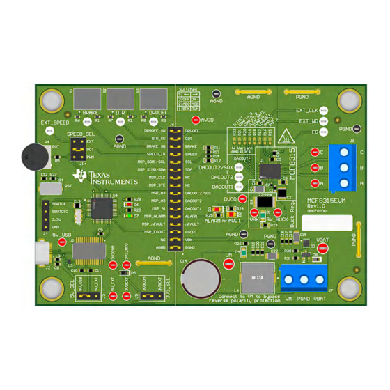
Page 3: Figure 1-2. Mcf8315Evm Jumper Configuration
Hall-effect sensors, leave these wires unconnected. Supply a voltage compliant with the Power Supply Voltage (VM) range using J7. Recommended voltage range for the device is 4.5 V – 35 V. SLLU363 – MAY 2023 MCF8315A Tuning Guide Submit Document Feedback Copyright © 2023 Texas Instruments Incorporated... -
Page 4: Figure 1-3. Mcf8315Evm External Configuration
MCF8315 device by clicking on the "Read All Registers" button on the top right of this GUI. After a few seconds, the GUI indicates with a pop-up notification that all registers have been read back successfully. MCF8315A Tuning Guide SLLU363 – MAY 2023 Submit Document Feedback Copyright © 2023 Texas Instruments Incorporated... -
Page 5: Essential Controls
Motor spin-up in closed loop. Closed loop is defined as the sensorless closed loop where motor spins at the commanded speed. 2.1 Recommended Default Values Launch the MCF8315A EVM GUI. Load the recommended default values that are listed in Table 2-1. -
Page 6: Control Configuration - Motor Parameters
Amps. The range of current limit values that can be configured in MCF8315A is between 0.078125 A and 5 A. If your motor current rating falls between two dropdown settings, then choose the higher setting. -
Page 7: Figure 2-1. Fault Status
Save the register settings by clicking File->Save Registers in the GUI. If there were no faults, skip to Section Figure 2-1. Fault Status SLLU363 – MAY 2023 MCF8315A Tuning Guide Submit Document Feedback Copyright © 2023 Texas Instruments Incorporated... -
Page 8: Fault Handling
This fault gets triggered when motor stalls while running in open loop for BEMF estimation. If this fault is triggered, then please follow the below suggestions. MCF8315A Tuning Guide SLLU363 – MAY 2023 Submit Document Feedback Copyright © 2023 Texas Instruments Incorporated... - Page 9 Ke. 2.6.4 Lock Current Limit [LOCK_LIMIT] This fault gets triggered when the motor is loaded above the stall torque of the motor. SLLU363 – MAY 2023 MCF8315A Tuning Guide Submit Document Feedback Copyright © 2023 Texas Instruments Incorporated...
-
Page 10: Figure 2-5. Phase Current Waveform Showing A Spike Due To Short Circuit
Step 1: Make sure the motor phases are connected to J5 or TP9, TP10, or TP11. Step 2: If the fault persists, set the No-Motor lock current threshold [NO_MTR_THR] to 0.03125A. MCF8315A Tuning Guide SLLU363 – MAY 2023 Submit Document Feedback Copyright © 2023 Texas Instruments Incorporated... -
Page 11: Basic Controls
[BRAKE_INPUT] to 10b overwrites Hardware pin and not low side brake/align. In Low side braking mode, all the LS FETs are turned ON. In Align braking mode, MCF8315A aligns a motor by injecting dc current through a particular phase pattern. -
Page 12: Figure 3-1. Phase Current And Fft - Dead Time Compensation Disabled
Step 2: When a command is issued for the motor to decelerate, based on the deceleration rate, the energy from motor pumps back to the power supply, increasing the supply voltage to possibly unsafe levels for electronics. MCF8315A Tuning Guide SLLU363 – MAY 2023 Submit Document Feedback Copyright © 2023 Texas Instruments Incorporated... -
Page 13: Control Configurations
3.3 Control Configurations 3.3.1 Motor Parameter Estimation to Minimize Motor Parameter Variation Effects The MCF8315A uses motor resistance, motor inductance and the motor Back-EMF constant to estimate motor position in closed loop operation. The MCF8315A has capability of automatically measuring motor parameters in offline state, rather than having the user enter the values themselves. -
Page 14: Constant
For example, ceiling fan motors have higher inertia due to the fan blades and can coast for long time before stopping. Step 1: Enable ISD [ISD_EN] Step 2: Enable Motor ISD Resynchronize [RESYNC_EN] MCF8315A Tuning Guide SLLU363 – MAY 2023 Submit Document Feedback Copyright © 2023 Texas Instruments Incorporated... -
Page 15: Figure 3-7. Reverse Drive Function
Reverse Deceleration Figure 3-7. Reverse Drive Function MCF8315A provides an option to apply brakes and stop the motor while the motor is coasting or spinning in reverse direction and then accelerate into closed loop after changing the direction. In applications such as ceiling fans and pumps, the requirement is to spin the motor in specific direction for desired results. - Page 16 Follow below steps if Slow first cycle is chosen as the startup method. Step 1: Select Slow first cycle in the Motor startup option [MTR_STARTUP] in “Control Configuration – Motor Startup Stationary” tab in the GUI. MCF8315A Tuning Guide SLLU363 – MAY 2023 Submit Document Feedback Copyright © 2023 Texas Instruments Incorporated...
- Page 17 Step 8: Keep increasing ramp rate for reducing difference between estimated theta and open loop theta to 2 deg/ms. Step 9: Increase Closed loop acceleration rate [CL_ACC] SLLU363 – MAY 2023 MCF8315A Tuning Guide Submit Document Feedback Copyright © 2023 Texas Instruments Incorporated...
- Page 18 Speed loop PI controller gains can either be auto-tuned by MCF8315A or tuned manually. Auto Tuning: MCF8315A auto calculates Speed loop PI controller gains when [SPD_LOOP_KP] and [SPD_LOOP_KI] are set to zero.
- Page 19 Increase lock detection current threshold [LOCK_ILIMIT] Note MCF8315A provides options to either latch LOCK_LIMIT fault or auto retry for [AUTO_RETRY_TIMES] after every [LCK_RETRY] seconds. This can be configured in [LOCK_ILIMIT_MODE]. We have defaulted the auto retry time and lock retry.
- Page 20 Note Modulation index [VOLT_MAG] can be read back from ALGO_STATUS register. Step 5: MCF8315A uses a PI controller to generate the D-axis reference current. Manually tune ACTIVE_BRAKE_KP and ACTIVE_BRAKE_KI if the active brake current looks unstable. MCF8315A Tuning Guide SLLU363 –...
- Page 21 TI products. TI’s provision of these resources does not expand or otherwise alter TI’s applicable warranties or warranty disclaimers for TI products. TI objects to and rejects any additional or different terms you may have proposed. IMPORTANT NOTICE Mailing Address: Texas Instruments, Post Office Box 655303, Dallas, Texas 75265 Copyright © 2023, Texas Instruments Incorporated...
Need help?
Do you have a question about the MCF8315A and is the answer not in the manual?
Questions and answers