Table of Contents
Advertisement
Quick Links
Advertisement
Table of Contents

Related Manuals for Mean Well RCP-1000


Summary of Contents for Mean Well RCP-1000
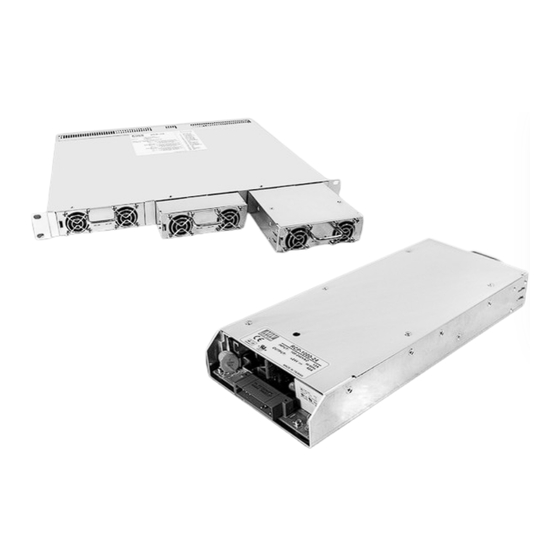
- Page 1 RCP-1000 / RCP-1U Instruction Manual...
-
Page 2: Table Of Contents
3.16 Hot-Swap Operation ..................... 3.17 Parallel Operation ....................... 3.18 Series Operation ....................... 3.19 Auxiliary Output ............3.20 Operation of I C Data Bus (RCP-1000-C models only) 4. Notes on Operation ......................................... 4.1 Installation Method ........................4.2 Derating ........................4.3 Warranty... -
Page 3: Safety Guidelines
◎Safety protection level of this unit is class I. The grounding wire should be firmly fixed at the "FG" terminal ( ) of the rack. The total leakage current of the rack system (including 3 * RCP-1000 units and 1 RCP-1U rack) is less than 3.5mA. -
Page 4: Main Specification
www. tuv.com ID 2000000000 ID 2000000000 Figure 1-2: Safety labels of RCP-1U□ ◎ □ Whole system (3 * RCP-1000 + RCP-1U ): CN500 CN500 ... -
Page 5: Mechanical Specification And Input / Output Terminals
◎ Rack system MODEL RCP-3K1U□-12 RCP-3K1U□-24 RCP-3K1U□-48 RECTIFIER RCP-1000-12 RCP-1000-24 RCP-1000-48 RACK SHELF RCP-1UI or RCP-1UT OUTPUT VOLTAGE OUTPUT MAX. OUTPUT CURRENT 180A 120A MAX. OUTPUT POWER 2160W 2880W 3024W Note.5 VOLTAGE RANGE 90 ~ 264VAC 127 ~ 370VDC Note.4... -
Page 6: Mechanism Of Whole Rack System
Input / Output Connector Pin. No Assignment(CN501) : Postronic PCIB24W9M400A1 Pin No. Assignment Pin No. Assignment Pin No. Assignment Pin No. Assignment Mating Housing AC_OK +5V_AUX 1,2,4 3,5,6 DC_OK GND_AUX Postronic ON/OFF PCIB24W9F400A1 V_TRIM AC/ L T_ALARM AC/ N Mechanism of Whole Rack System Address CN500 Switch... -
Page 7: Functions
3.5.1 Adjustment of single unit Output voltage of one RCP-1000 is adjustable through the potentiometer (SVR51, can be found under the small circular hole on top of the unit). Please use a cross-screwdriver with isolated holder to make the adjustment. - Page 8 The resistors R1, R2 mentioned in Figure 3-1 should be added independently and the minimum wattage rating is 0.1W. Please refer to 3.5.4~3.5.6 about the selection of resistance. 3.5.4 Reference resistance value of R1/R2 for RCP-1000-12 Vout (%) Vout (%) R1 (Ω)
-
Page 9: Fan Speed Control
Over Temperature Alarm ◎ Every RCP-1000 single unit has a detecting circuit to sense its internal temperature. The value of internal temperature can ℃± ℃ only be read through the I C interface: when the internal temperature of RCP-1000 is higher than 60 3 , there will be an alarm signal sent out through the I C interface. -
Page 10: Hot-Swap Operation
Figure 3-6: Location of the "clip" on RCP-1000 unit 3.17 Parallel Operation 3.17.1 Operation of single rack ◎ Internal parallel operation in single rack is only suitable for using the same RCP-1000 unit (single unit with the same output voltage and current). ◎ □... -
Page 11: Series Operation
◎ Higher output voltage can be acquired by connecting different racks in series. ◎ The racks □ connected in series should have the same single unit (RCP-1000-□) in each rack. Please refer to (RCP-1U ) Figure 3-8 for the reference connection method. - Page 12 In addition, each RCP-1000 unit should have its unique device address to communicate over the bus. The address can be assigned by the 9-pole DIP switch on the rack. In one RCP-1U rack, there are a total of 3 RCP-1000 units, and each RCP-1000 has a 3-pole addressing switch (refer to the following diagram).
- Page 13 (1)The DIP switch is used for the bus device addressing configuration. Poles 1 to 3 are for setting the address of the A module, poles 4 to 6 are for the B module, and poles 7 to 9 are for the C module. Module DIP switch position...
- Page 14 Temperature 0~100℃ 0.391 /bit For example, if the temperature reading value of RCP-1000-24 is "0x52", then convert to decimal value will be "82". 82(value) x 0.391(resolution for 24V temperature) = 32.062℃ 3.Reading example Read output current data of Output & Temperature from the RCP-1000-48 unit with address "0".
- Page 15 The following example will explain how to read the Operational Status and output voltage of Output & Temperature from a RCP-1000-48C. 1.Set the address of the RCP-1000-48C to "0". If installed in the far right slot of a RCP-1U , set poles 1-3 of the 9-pole DIP switch (ADDRESS SWITCH) to the ON/ON/ON positions.
-
Page 16: Notes On Operation
◎ This is a power supply with built-in DC fan and please make sure that the ventilation is not blocked. It is suggested that there should be no barriers within 10cm of the ventilating holes. ◎ Connect AC source to the AC input for A, B, C module position respectively depending on the RCP-1000 units assembled into □ the RCP-1U rack. -
Page 17: Derating
Warranty ◎Three years of global warranty is provided for RCP series under normal operation. Please do not change any component or modify the unit by yourself or MEAN WELL may reserve the right not to provide the complete warranty service. - Page 18 N o . 2 8 , W u q u a n 3 r d R d . , W u g u D i s t . , N e w Ta i p e i C i t y 2 4 8 , Ta i w a n...
Need help?
Do you have a question about the RCP-1000 and is the answer not in the manual?
Questions and answers