Table of Contents
Advertisement
Quick Links
Advertisement
Table of Contents

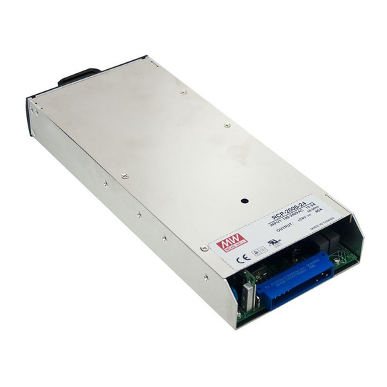
Summary of Contents for Mean Well RCP-2000
- Page 1 RCP-2000 / RKP-1U I n s t r u c t i o n M a n u a l...
-
Page 2: Table Of Contents
0.Safety Guidelines......................1.Introduction of Series Models........................................ 1.1 Introduction ........................1.2 Features ......................1.3 Order Information ....................... 1.4 Main Specification 2.Mechanical Specification and Input / Output Terminals............................2.1 Mechanism of Single Unit .................. 2.2 Mechanism of Whole Rack System 3.Functions........................ -
Page 3: Safety Guidelines
RCP-2000 or RKP-1U by yourself! ◎Please do not change any component on the RCP-2000 series by yourself or make any kind of modification on it. ◎Please do not install the RCP-2000 series in places with high moisture, high ambient temperature or under direct sunlight. -
Page 4: Main Specification
FREQUENCY RANGE 47 ~ 63Hz POWER FACTOR (Typ.) 0.98/230VAC at full load EFFICIENCY (Typ.) INPUT 90.5% AC CURRENT (Typ.) 13A/115VAC 7A/230VAC 16A/115VAC 10A/230VAC 16A/115VAC 10A/230VAC INRUSH CURRENT (Typ.) COLD START 50A LEAKAGE CURRENT <1.1mA / 230VAC 105 ~ 125% rated output power OVERLOAD Protection type : Constant current limiting, unit will shut down o/p voltage after 5 sec. -
Page 5: Mechanical Specification And Input / Output Terminals
5. Derating may be needed under low input voltages. Please check the derating curve for more details. 6. Output of all the RCP-2000 modules are connected in parallel in the rack. 7. Under parallel operation of more than one rack connecting together, ripple of the output voltage may be higher than the SPEC at light load condition. -
Page 6: Mechanism Of Whole Rack System
Input / Output Connector Pin No. Assignment(CN501) : Postronic PCIM34W13M400A1 Pin No. Assignment Pin No. Assignment Pin No. Assignment Pin No. Assignment Pin No. Assignment Pin No. Assignment Mating Housing ON/OFF T-ALARM 1,2,3,4 5,6,7,8 FAN-FAIL AC/L Postronic -V(signal) +5V-AUX AC/N PCIM34W13F400A1 +V(signal) AC-OK... -
Page 7: Functions
◎Connector Pin No. Assignment of CN500 Pin No. Assignment Pin No. Assignment Pin No. Assignment Pin No. Assignment Pin No. Assignment ON/OFF-A FAN FAIL-A T-ALARM-B ON/OFF-C FAN FAIL-C AC-OK-A ON/OFF-B FAN FAIL-B AC-OK-C DC-OK-A AC-OK-B +5V-AUX DC-OK-C PV-A DC-OK-B +12V-AUX PV-C T-ALARM-A PV-B... -
Page 9: Over Voltage Protection (O.v.p.)
In the mean time, there will be a "High" signal (4.5~5.5V) between "FAN FAIL" and "GND-AUX" on CN500 connector. Please switch off the AC source and send back to our local distributor or MEAN WELL for repair. ◎The sourcing current is 10mA and only for output. -
Page 12: Auxiliary Output
DIP switch position Table 3-1 3.19.2 PMBus Command List ◎Table 3-2 shows the command list of RCP-2000. It is compliant with industry standard PMBus protocol Rev. 1.1. For more details about the information, you can refer to PMBus official web ( http://pmbus.org/specs.html... - Page 13 Command Command Transaction # of data Description Code Name Type Bytes Output voltage trimming value VOUT_TRIM R/W Word (format: Linear, N= -9) Output overcurrent setting value IOUT_OC_FAULT_LIMIT R/W Word Define protection and response when an IOUT_OC_FAULT_RESPONSE R Byte output overcurrent fault occurred STATUS_WORD R Word Summary status reporting...
- Page 14 Table 3-7 2.If RCP-2000 units is restarted, the parameters of Bus voltage and PSU current you have set will return to the initial/default values, whereas if RCP-2000 units is connected with a RKP-CMU1 unit, the restarted RCP-2000s will be loaded the previous set parameters by the RKP-CMU1 automatically.
-
Page 15: Notes On Operation
RKP-1UT 1 2 3 4 5 AC Input(C) AC Input(B) AC Input(A) ADDRESS ADDRESS ADDRESS DCOutput SWITCH SWITCH SWITCH CN500 RKP-1UI Mounting Bracket IEC320-C20 IEC320-C20 IEC320-C20 SVR1 SVR1 SVR1 Air flow direction Module C Module B Module A 10.2 DC OK DC OK DC OK 466.1... -
Page 16: Derating
Table 4-1 Suggested wire selection for input / output wirings Derating ◎When RCP-2000 units are operating in high ambient temperature or at a low AC input voltage, these units will de-rate their output current automatically to protec themselves, as shown in Figure 4-2.


Need help?
Do you have a question about the RCP-2000 and is the answer not in the manual?
Questions and answers