
Related Manuals for Mean Well RCB-1600


Summary of Contents for Mean Well RCB-1600
- Page 1 RCB-1600-RHP-1U_1610-21407-0001-E-0420 RCP- 00 / RCB -1600 / RHP-1U U s e r ' s M a n u a l...
-
Page 2: Table Of Contents
......................3.18 Auxiliary Power ............... 3.19 RCP-1600 PMBus Communication Interface ............. 3.20 RCB-1600 PMBus Communication Interface ..............3.21 CANBus Communication Interface ......................Notes on Operation ....................... Installation Method ........................ -
Page 3: Safety Guidelines
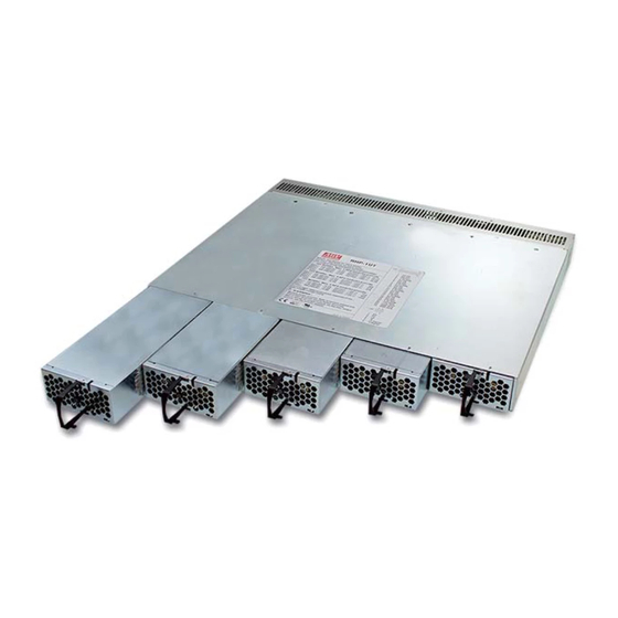
The RCP-1600 is a rack mountable power supply that provides energy source for telecom equipments, monitoring systems, severs, etc, installing into a 19" rack shelf is required for operation . The RCB-1600 is a rack mountable charger, used to charge batteries, installing into a 19" rack shelf is required operation. 1.2 Features Description ◎... -
Page 4: Main Specification
RCB-1600-RHP-1U_1610-21407-0001-E-0420 ◎Rack Shelf : RHP-1UI-A RHP-1UT-A Use only RCP-1600 or RCB-1600 series of identical model. Use only RCP-1600 or RCB-1600 series of identical model. RCP-1600 series RCB-1600 series RCP-1600 series RCB-1600 series □ 48V MODEL, Max. 5 modules provide □ 48V MODEL, Max. 5 modules provide □... - Page 5 RCB-1600-RHP-1U_1610-21407-0001-E-0420 MODEL RCB-1600-12 RCB-1600-24 RCB-1600-48 BOOST CHARGE VOLTAGE(Vboost)(default) 14.4V 28.8V 57.6V FLOAT CHARGE VOLTAGE(Vfloat)(default) 13.8V 27.6V 55.2V CURRENT RANGE 0 ~ 100A 0 ~ 55A 0 ~ 27.5A CONSTANT CURRENT(CC)(default) 100A 27.5A RATED POWER 1440W 1584W 1584W By built-in potentiometer, SVR OUTPUT VOLTAGE ADJ.
-
Page 6: Mechanical Specification And Inpit/Out Terminals
EMC tests, please refer to “EMI testing of component power supplies.” (as available on http://www.meanwell.com) 4. Output of all the RCB-1600 modules are connected in parallel in the rack. 5. The equivalent leakage current of the system is determined by the quantity of populated rectifiers. -
Page 7: Mechanism Of Whole Rack System
RCB-1600-RHP-1U_1610-21407-0001-E-0420 2.2 Mechanism of whole Rack system ADDRESS ADDRESS ADDRESS ADDRESS ADDRESS SWITCH SWITCH SWITCH SWITCH SWITCH RHP-1UT 4-M8 L=16 ADDRESS ADDRESS ADDRESS ADDRESS ADDRESS SWITCH SWITCH SWITCH SWITCH SWITCH RHP-1UI IEC320-C14 4-M8 L=16 IEC320-C14 IEC320-C14 IEC320-C14 IEC320-C14 5-M4 L=4 5-M4 L=4 20.7... - Page 8 60 ; under this condition, the unit still operates normally without entering Red Flashing OT . (In the meantime, an alarm signal will be sent out through the PMBus LED Status Indicator interface.) Figure 2-3 RCP/RCB-1600 front panel For charger system Description Green Float(stage 3)
-
Page 9: Functions
For charger system RTH+ Temperature sense associated with the temperature compensation funcion. RTH- Not use. ◎ The Black wiring cable goes with the RCB-1600, used for battery temperature compensation. ※ Connector Pin No. Assignment( ) : RJ45 8 positions Pin No. Function... - Page 10 Output current adjustment (Output current trimming function ※ Constant current level(RCP-1600)/output current (RCB-1600) can be adjusted within a range of 20-100% of the rated current via an external DC source, the wiring is show as below. CN2 +S LOAD RHP-1U System...
-
Page 11: Fan Speed Control
Built-in fan-lock protection circuit, the output will shut off when the DC fans stop operating (fan-lock or broken wires). In the meantime, there will be a “HIGH” signal sent out through T-ALARM, referenced to GND AUX. Please remove the unit from your system and send back to our local distributor or MEAN WELL for repair. ◎... -
Page 12: Hot-Swap Operation
Insert units: Grasp the handle and push into the rack shelf through the rail. "Click" Figure 3-6 Illustration of how to insert the RCP/RCB-1600 into a rack ◎ Pull out units: Press the clip shown in Figure 3-7 and pull it out. -
Page 13: Series Operation
RCB-1600-RHP-1U_1610-21407-0001-E-0420 3.16.2 Operation of three rack shelves in parallel (RCP-1600 system) ◎ Parallel operation is only suitable for the identical units (with the same model and the same output voltage/current). Up to 3 rack shelves and the maximum supply units that can be connected in parallel is 15. -
Page 14: Auxiliary Power
RCB-1600-RHP-1U_1610-21407-0001-E-0420 3.18 Auxiliary Output ◎ Built-in 5V/0.3A and 12V/0.8A auxiliary output. 3.19 RCP-1600 PMBus Communication Interface ◎ RCP-1600 is compliant with PMBus Rev.1.1, the maximum communication speed is 100KHz and it has the capability of identifying up to16 addressed units. - Page 15 RCB-1600-RHP-1U_1610-21407-0001-E-0420 3.19.2 PMBus Command List ◎ The command list of the RCP-1600 is shown in Table 3- . It is compliant with the standard protocol of PMBus Rev. 1.1. For more detailed information, please refer to PMBus official website http://pmbus.org/specs.html).
-
Page 16: Rcb-1600 Pmbus Communication Interface
3.20 RCB-1600 PMBus Communication Interface ◎ RCB-1600 is compliant with PMBus Rev.1.1, the maximum communication speed is 100KHz and it has the capability of identifying up to 8 addressed units. ◎ PMBus communication interface is able to provide the current operating status and data as the following: 1.Output voltage, current and internal temperature. - Page 17 1 2 3 4 The charging operation can be determined by the setup over D0, position 4 on the DIP switch. When D0 is “ON”, RCB-1600 follows a built charging curve to charge the batteries; when D0 is “OFF”, the charging operation is completely defined by the control over PMBus, PV/PC or SVR. Please refer to Table 3-7 (right).
- Page 18 RCB-1600-RHP-1U_1610-21407-0001-E-0420 3.20.3 PMBUS, PV/PC or SVR Functions Users are able to fully control and design the entire charging behavior, without the charging curve, by one of the following means- PMBus command, PV/PC function or SVR adjustment, please refer to the previous chapter. The operating priority is, PMBus > PV/PC > SVR.
- Page 19 RCB-1600-RHP-1U_1610-21407-0001-E-0420 Command Command Transaction # of data Description Code Name Type Bytes Constant current setting value of charging curve CURVE_ICHG R/W Word (format: Linear, N= -2) Constant voltage setting value of charging curve CURVE_VBST R/W Word (format: Linear, N= -9)
- Page 20 RCB-1600-RHP-1U_1610-21407-0001-E-0420 ◎ Definition of Command B8h CHG_STATUS: Bit7 Bit6 Bit5 Bit4 Bit3 Bit2 Bit1 Bit0 High byte FVTOF CVTOF CCTOF BTNC NTCER EEPER Low byte FULLM Low byte Bit 0 FULLM:Fully Charged ode Status 0=NOT fully charged 1=fully charged Bit 1 CCM:Constant Current Mode Status...
- Page 21 RCB-1600-RHP-1U_1610-21407-0001-E-0420 3.20.5 PMBus Data Range and Tolerance ◎ Display parameters PMBus command Mode Range Tolerance ±10V READ_VIN 80 ~ 264V ±0.18V 0 ~ 15V ±0.36V READ_VOUT 0 ~ 30V ±0.48V 0 ~ 60V ±2.5A 0 ~ 150A READ_IOUT ±1.34A 0 ~ 80A (Note.1)
-
Page 22: Notes On Operation
When using PMBus to adjust output voltage, VOUT_COMMAND only can be used to display the rated voltage of the unit and cannot be written. It is VOUT_TRIM that provide voltage trimming function. Taking RCB-1600-12 as an example, to get a 9V output, please value of VOUT_TRIM to -3V. Adjustable voltage range for each model is shown as below. -
Page 23: Derating
RCB-1600-RHP-1U_1610-21407-0001-E-0420 De-rating ◎ When RCP-1600/RCB-1600 units are operating at a lower AC input voltage, these units will de-rate their output current automatically to protect themselves, shown as Figure 4-2. 230VAC Input only (HORIZONTAL) ℃ AMBIENT TEMPERATURE ( ) INPUT VOLTAGE (VAC) 60Hz... - Page 24 We are here for you. Addresses and Contacts. Headquarter Switzerland: Office Germany: Angst+Pfister Sensors and Power AG Angst+Pfister Sensors and Power Deutschland GmbH Thurgauerstrasse 66 Edisonstraße 16 CH-8050 Zurich D-85716 Unterschleißheim Phone +41 44 877 35 00 Phone +49 89 374 288 87 00 sensorsandpower@angst-pfister.com sensorsandpower.de@angst-pfister.com Scan here and get an overview of personal contacts!
Need help?
Do you have a question about the RCB-1600 and is the answer not in the manual?
Questions and answers