Table of Contents
Advertisement
Quick Links
Advertisement
Table of Contents

Related Manuals for Mean Well RKP-CMU1


Summary of Contents for Mean Well RKP-CMU1
- Page 1 RKP-CMU1 / RKP-1U-CMU1 Instruction Manual...
-
Page 2: Table Of Contents
..................Notes on PMBus Monitoring ......................Parallel Operati ....................... 3.10 Series Operation 4.RKP-CMU1 LCD User Interface.............................. 4.1 Description of RKP-CMU1 Front Panel ..................... 4.2 LCD Display ..................... 4.3 Status Menu ......................4.4 Setting ..................... 4.5 Maintenance Menu ....................4.6 Network Menu 5.RKP-CMU1 Web Page Monitoring... - Page 3 6.RKP-CMU1 Monitoring Software....................................6.1 Installation ............6.2 Using RS232 for Communication with RKP-CMU1 ............6.3 Description of RKP-CMU1 Monitoring Software 7.GSM Short Message Functions..................................7.1 Installation and Settings ................7.2 Test of Sending a Short Message ................7.3 AT-Command List for RKP-CMU1 Notes on Operation ......................
-
Page 4: Safety Guidelines
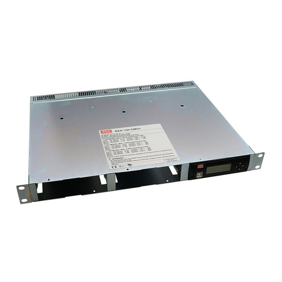
1.Introduction of Series Models Introduction The RKP-CMU1 is a dedicated monitor unit for RCP-2000 series. It provides the management task of RCP-2000 for using in telecommunication, monitoring systems, servers, etc. It can be stand-alone operated or integrated into a 19-inch rack. -
Page 5: Main Specification
www. tuv.com ID 2000000000 ID 2000000000 Figure1-2: Safety Labels of RKP-1U□-CMU1 ◎Whole system (2*RCP-2000 + 1*RKP-CMU1 + RKP-1U□) : □ □ ... -
Page 6: Mechanical Specification And Input/ Output Terminals
2.Mechanical Specification and Input/ Output Terminals Mechanism of Single Unit 40.9 2-M3 L=6mm 147.5 Fig1 40.9 2-M3 L=6mm 40.9 2-M3 L=6mm BOTTOM VIEW Figure 2-1... -
Page 7: Mechanism Of Whole Rack System
Mechanism of Whole Rack System Fig1 Fig2 ADDRESS ADDRESS SWITCH SWITCH CN500 SK100 Fig3 RKP-1UT-CMU1 1 2 3 4 5 JK500 CN503 CN502 ADDRESS ADDRESS SWITCH SWITCH CN500 SK100 RKP-1UI-CMU1 Mounting Bracket JK500 CN503 CN502 IEC320-C20 IEC320-C20 SVR1 SVR1 Air flow direction Module B Module A... - Page 8 ◎JK1 Pin No. Assignment Connector Pin No. Assignment(JK1) : RJ45 8 positions Pin No. Assignment Pin No. Assignment Pin No. Assignment CONTROL GND-AUX ◎CN502 Pin No. Assignment Connector Pin No. Assignment(CN502) : D-type Male 9 positions Pin No. Assignment Pin No. Assignment 1,4,6,7,8,9 GND-FG...
-
Page 9: Functions
ON/OFF" must be opened from +5V-AUX to avoid interfering in RKP-CMU1's proper operation. 3.2 LED Indicators and LCD User Interface There are LED indicators on the front panel of the RKP-CMU1 that are used to display system operating status. Refer to Table 3-2 for details. Status Description Power on indicator of RKP-CMU1. -
Page 10: Communication And Operation Interface
3.4 Real Time Clock, Data Log and Event Log The RKP-CMU1 has a built-in real time clock to display actual date/time for log timestamp. The Data Log is used to store the operating data of the rack power system. It has 1000 records and the interval of log is programmable from 1 to 60 minutes. -
Page 11: Pmbus Communication Interface
3.7 PMBus Communication Interface The RKP-CMU1 is equipped with all the PMBus commands that RCP-2000 needs. This makes it easy for users to monitor, manage, and control their RCP-2000 power systems by means of the LCD user interface or the Windows based user interface. Moreover, the unit is compliant with PMBus Rev. - Page 12 3.7.3 PMBus Data Range and Tolerance All of the PMBus data are fully digitalized. The RKP-CMU1 uses the data read from RCP-2000 units to display their operating values and control these units. Please refer to the definition of RCP-2000, as shown below, for Display / Control tolerance.
-
Page 13: Notes On Pmbus Monitoring
3.Using the RKP-CMU1 to reduce PSU current will just limit output current of RCP-2000 units and will not trigger their over-current alarm. Take RCP-2000-48 as an example, the over-current protection threshold is 47A when operating at 230Vac. - Page 14 Figure 3-2 Configuration of a RKP-1U-CMU1 and two RKP-1Us 3.9.3 Using RKP-CMU1 to monitor RKP-1Us ◎RKP-CMU1 is capable of monitoring and controlling up to tree RKP-1Us (nine RCP-2000 units). Please refer to the user's manual of RCP-2000/RKP-1U and Figure 3-3 for notes on parallel operation of RKP-1Us.
-
Page 15: Series Operation
3.10 Series Operation The RKP-CMU1 is specifically designed to monitor, manage, and control RCP-2000 units in parallel. As a result, it cannot be used for RCP-2000 units connected in series. If you do need this application, contact our distributors or MEANWELL for details. -
Page 16: Status Menu
Under the "Status Menu", status information, including Bus voltage, total output current, numbers of PSUs in parallel, PSU current, PSU temperature, PSU status, PSU serial number, PSU manufacture date, PSU firmware version, condition of digital input signal, condition of programmable relay, date, and RKP-CMU1 information, can be selected through the "UP"/"DOWN" buttons. 4.3.1 Bus Voltage... - Page 17 4.3.3 Numbers of PSUs in Parallel 4.3.4 PSU Current In the "PSU Current" section, each of the PSU's output currents can be displayed by pressing the "ENT" button. Once you entered this page, you can choose one of the PSU's output currents to be displayed on the screen through the "UP"/"DOWN"...
- Page 18 Once you entered this page, you can choose one of the PSU's statuses to be displayed on the screen through the "UP"/ "DOWN" buttons. "xx" indicates PSU's number. If an abnormal situation occurs, the screen will display which PSU unit is and its situation, no matter which unit you have chosen.
-
Page 19: Setting
COM contacts the "NC". "o" indicates that the relay is activated, and its COM is contacting the "NO". 4.3.12 RKP-CMU1 Information In the "RKP-CMU1 Info." section, there are the serial number, the manufacture date, the firmware version, country of production, and the GSM phone number of the RKP-CMU1 that can be displayed by pressing the "ENT" button. - Page 20 Once you entered this screen, you can choose which PSU you would like to turn on or off through the "UP"/"DOWN" buttons. It is also possible to control the whole units by changing "xxx" to "ALL". "xxx" indicates PSU's number. If "OFF (Alarm)", or "N/A"...
- Page 21 Once you entered this page, you can trim the output current through the "UP"/"DOWN" buttons. Refer to the Table of PSU adjustable current range. PSU adjustable current range: Model PSU Current Range Default 30 ~ 112A 112A 24 ~ 89.6A 89.6A 12.6 ~ 47A Note : If the set PSU current exceeds 100A, the maximum rated current, OTP might be triggered after operating a period...
-
Page 22: Maintenance Menu
Under "Buzzer Control", you can turn buzzer on or off by pressing the "ENT" button. (Default: ON Buzzer) 4.4.9 RKP-CMU1 Address Setting In the "RKP-CMU1 address" section, you can set RKP-CMU1's address by pressing the "ENT" button. (Default: 1) 4.5 Maintenance Menu A password is required to enter this menu. -
Page 23: Network Menu
Each RKP-CMU1 unit has a different MAC address, and the address is assigned by the internal hardware. 4.6.2 IP Address IP address can be changed by the built-in web page, but doing so requires the RKP-CMU1 and the PC you use in the same domain. (Default IP: 169.254.1.1) 4.6.3 Subnet Mask... -
Page 24: Rkp-Cmu1 Web Page Monitoring Functions
RJ-45 cable ◎Before accessing the built-in web page, please make sure that the RKP-CMU1 and the PC you use are set in the same domain. If this is the first time you access the built-in web page, you will need to change the IP address of your PC. Once you connected the built-in web page, change of the RKP-CMU1's address settings (like to another domain) can be done. - Page 25 (4) Check if it is working correctly by clicking the "Support". If the addresses presented as you typed, it is successfully done. Then you can access the built-in web page. If the table shows as below, it means that your RJ-45 cable is not properly connected or the IP address you have set is incorrect.
-
Page 26: Description Of Rkp-Cum1 Built-In Web Page
Connect your PC to the RKP-CMU1, then open a blank page and type the IP address of the RKP-CMU1 in the address bar. If you are not sure the IP address of RKP-CMU1, refer to the LCD user interface. The route is "Main Page" → "Menu Page" →... - Page 27 5.2.3 PSU Status Page The "PSU Status" page displays the operating information of each PSU, including output current, internal temperature, serial number, firmware version, alarm, and status. 5.2.4 Configuration Page Once you clicked the "Configuration" page, you will be asked to enter a user name and a password. Type "meanwell" (small letters) in both the "User name"...
- Page 28 Once you insert the correct user name and password, you will enter the settings page. On this page, there are Bus voltage, PSU over-current, clear Event Log/Data Log, Data Log time interval setting, programmable relay setting, and PSU ON/OFF that can be set and altered. 5.2.4.1 Bus Voltage / PSU Current If the Bus voltage/PSU current you set is not within the adjustable range, it will become invalid.
-
Page 29: Event Log Page
If a status bar displays "N/A", it cannot be controlled due to non-connection to the RKP-CMU1. Turning the whole PSU units on or off is also possible by clicking the "ALL PSU ON"/ "ALL PSU OFF"... -
Page 30: Data Log Page
5.4 Data Log Page The Data Log will save operating data at regular intervals set by "Data log interval". The Data Log is capable of saving 1000 records, but if the stored data is over its capacity, it will overwrite the previous data, from the first record. The contents that Data Log stores include AC voltage, relay condition, condition of digital input signal, output voltage, total output current, each PSU's currents, and time. -
Page 31: Rkp-Cmu1 Monitoring Software
DNS, and secondary DNS that can be set and changed. For example, if the RKP-CMU1 is not in your current domain, you can revise it to your current domain by changing those IP address parameters. -
Page 32: Using Rs232 For Communication With Rkp-Cmu1
The RKP-CMU1 not only can use USB interface for PC connection, but also can use the RS-232 interface. There is a RS-232 port (Male) on the rear of the RKP-CMU1, you can use a DB9 Female - DB9 Female cable for connection between the RKP-CMU1 and your PC. - Page 33 RKP-CMU1, it will display "COMx Connected". If a connection failed, it will display "Comm. fail". Connection was successful. Connection failed. Make sure the interface cable is properly connected between your PC and the RKP-CMU1, and make sure the parameters you set are correct.
- Page 34 6.3.3 PSU Status Page The "PSU Status" page displays the operating information of each PSU, including output current, internal temperature, serial number, firmware version, alarm, and status. 6.3.4 Config. Page On this page, there are Bus voltage, PSU current, clear Event Log/Data Log, Data Log time interval setting, programmable relay setting, and PSU ON/OFF that can be set and altered.
- Page 35 ON", "OFF(red)" indicates "PSU OFF", and "N/A(orange)" indicates "unconnected". Once you have chosen a PSU, you can click the "ON" or "OFF" buttons to turn it on/off. If the status column displays "N/A(orange)", it cannot be controlled due to non-connection to the RKP-CMU1.
- Page 36 Status table Scroll-down list and setting buttons 6.3.5 Event Log Page The Event Log stores abnormal system situations when alarms occur. It is capable of saving up to 600 records, but if the stored data is over its capacity, it will overwrite the previous data, from the first record. The contents that Event Log stores include time, type of alarm, and which PSU it is.
- Page 37 After reading from the RKP-CMU1, the data will be arranged in ascending order of Log No.. Sorting the data into other orders is also possible by clicking the column headers. Clicking the "Save Log" button can save the data onto your PC.
- Page 38 Sorting data can be done by clicking a column header Save button Chart button This page also offers a function that presents the Data log data in column charts by clicking the "Chart" button. Once column charts are created, tendency of the data can be seen on your PC. Except for "Vbus" and "Iout" that are fixed on the page, others like I0~I7 (PSU0~7 Iout), I8~I15 (PSU8~15 Iout), I16~I31 (PSU16~31 Iout), and Vac max/min (the maximum/ minimum AC input) can be selected by the "scroll-down list".
-
Page 39: Gsm Short Message Functions
(1) Insert a SIM card into your GSM modem. Make sure that there is no PIN (Personal Identification Number) recorded in the SIM card. (2) After installing a GSM antenna to your GSM modem and connecting an interface cable between the RKP-CMU1 and your GSM modem, turn the GSM modem on. -
Page 40: Test Of Sending A Short Message
(1) Turn devices on in the following order: RCP-2000, RKP-CMU1, and then GSM modem. (2) Unplug the power of the RCP-2000. (3) In this case, there is a "PMBus Error" alarm that will occur. Then, you should receive a text message sent by the RKP-CMU1 after a few seconds. -
Page 41: Notes On Operation
◎Mount the RKP-CMU1 in a 19" rack before operating. ◎Connect the RKP-CMU1 to a JK1 port of a rack unit. Also, make sure that the JK1 ports are connected together if there are more than 2 rack units. Refer to Figure 3.3. - Page 42 ◎Recommended input/output wires are in Table 8-1. ◎Wire up your interface cable (USB/RS232), programmable relays, and digital input signals, depending on your application. ◎Apply a 12~15 VDC to the SK100 port on the rear of the RKP-CMU1 in order to power on RKP-CMU1. Fig1...
-
Page 43: Rating
◎Three years of global warranty is provided for RCP 2000 series/ RKP-CMU1 under normal operation. Please do not change any component or modify the unit by yourself or MEAN WELL may reserve the right not to provide the complete warranty service.
Need help?
Do you have a question about the RKP-CMU1 and is the answer not in the manual?
Questions and answers