Table of Contents
Advertisement
Quick Links
Download this manual
See also:
User Manual
Winmate FM10A
Vehicle Mounted Computer
Android 4.4
Quick Start Guide
For more information on this and other
Winmate products, please visit our
website at:
www.winmate.com
Version III
Document Part Number: 9152111I101B
Please read these instructions carefully before using this product, and save this manual for future use.
Advertisement
Table of Contents

Subscribe to Our Youtube Channel
Related Manuals for Winmate FM10A


Summary of Contents for Winmate FM10A
-
Page 1: Quick Start Guide
Winmate FM10A Vehicle Mounted Computer Android 4.4 Quick Start Guide For more information on this and other Winmate products, please visit our website at: www.winmate.com Version III Document Part Number: 9152111I101B Please read these instructions carefully before using this product, and save this manual for future use. -
Page 2: Table Of Contents
- 6 - b. Optional Accessories - 7 - II. Components - 8 - III. Winmate® Key Mapping (WKM) - 10 - IV. Docking and Undocking the Device - 12 - a. Docking the device into vehicle dock - 12 - b. - Page 3 Warranty Winmate Inc. warrants that each of its products is free from material and workmanship defect for a period of one year starting from the invoice date. If the customer discovers a defect, Winmate Inc.
-
Page 4: Fcc Regulations
FCC Regulations This device complies with part 15 of the FCC Rules. Operation is subject to the following two conditions: (1) This device may not cause harmful interference, and (2) this device must accept any interference received, including interference that may cause undesired operation. This device has been tested and found to comply with the limits for a Class B digital device, pursuant to Part 15 of the FCC Rules. - Page 5 IC Regulations Le présent appareil est conforme aux CNR d’Industrie Canada applicables aux appareils radio exempts de licence. L’exploitation est autorisée aux deux conditions suivantes: l’appareil ne doit pas produire de brouillage, et l’utilisateur de l’appareil doit accepter tout brouillage radioélectrique subi, même si le brouillage est susceptible d’en compromettre le fonctionnement.”...
-
Page 6: Unpacking
Before using this device, make sure that all the items listed below are present in your package: USB to RS232 & 5 m Power Computer Dock + Latch 0.3 m USB USB A Type Cable with Fuse FM10A Locking Key Cable Cable 98P010A000J7 98D000A0000A 98K000A0006O 9484098080K0 94E3098130K0... -
Page 7: Optional Accessories
(VM240) Combo Antenna (VM10S) 39700000000M 39700000000N 39700000000U 98K000A0005Y 98K000A0006P Mounting Kit 3 1.8 m Keyboard CAN Bus Y Cable Mounting 98K000A0005X 94E2150090K0 It is highly recommended to purchase a power cable from Winmate Note for testing purposes - 7 -... -
Page 8: Components
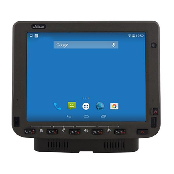
II. Components Front View The integrated keypad contains 10 programmable keys, the F1 through F10 keys are user programmable. Key mapping is configured via the hot tab option in the control panel. See programmable key to remap these keys. The default values for these keys are: Function Key Default Key Value F1 + F2... - Page 9 Rear View with Vehicle Dock Left Side View with Vehicle Dock Right Side View with Vehicle Dock - 9 -...
-
Page 10: Winmate® Key Mapping (Wkm)
III. Winmate® Key Mapping (WKM) Winmate® FM10A Vehicle Mounted Computer comes with preinstalled APP called Winmate® Key Mapping (WKM) which let users to assign functions of function keys F1 ~ F10. Open Winmate® Key Mapping (WKM) application ( You can set the application which the favorite you want as a shortcut in corresponding key. - Page 11 In Application Selector window, click F1 to open the drop-down menu of function keys. In this example, we have selected to set up functions for F1 function key. Choose the function key and then select a Default application that will be opened by pressing on the function key you’ve selected.
-
Page 12: Docking And Undocking The Device
IV. Docking and Undocking the Device a. Docking the device into vehicle dock To dock the device, perform the following: 1. With the device screen side facing out, align and insert the device into the guide pins on the vehicle dock. 2. -
Page 13: Connecting The Power Cable For Office Testing
This procedure require a trained service personnel only, Warning improper installation can cause serious damage to the vehicle or the device a. Connecting the power cable for office testing Users are highly recommended to purchase this power cable for Note testing purpose 1. - Page 14 Select a mounting location and make sure it is not located on Warning the outside the vehicle Color Symbol VCC+ Black VCC- Green Ground Blue Ignition input (optional) Do not perform the installation on a moving or live electric Warning forklift 1.
- Page 15 Warning All power wiring must use the supplied power cable 4. Slide tubing over wires , remove the wires and insert it to the fuse holder, crimp it wire to the vehicle’s positive power source. Connect the black wire 5. Connect the to the vehicle’s negative power source.
- Page 16 7 Secure the power cable to the device using cable clamps and place the device in the dock. See Power cable routing below. Use the proper cable clamps and not to over tighten it to Warning prevent it from break 8 Press the power switch on the back of the dock See Power switch.
-
Page 17: Power On Behavior
VI. Power on Behavior The table below shows the Ignition control power scheme on the vehicle installation and office test. Vehicle Installation Power On Office Test / Evaluation Behavior With Ignition Without Ignition Default ‘0” sec” Default ‘”0 sec” Default ‘”0 sec” Ignition delay Adjustable from 0-120 sec, through application. -
Page 18: Power Button
The Power button is located at lower right of the FM10A. Note • The FM10A needs to be docked in a powered vehicle dock or UPS battery has a sufficient charge to power on the device. • If no external power available and the UPS... -
Page 19: Standby / Wakeup Behavior
b. Standby / Wakeup Behavior Power Button Action Button Indicator Backlight Press the On button for “2 seconds” until the screen On and Standby or then release the button. The Sleep Mode battery indicator will Off after the screen is Off, the system is already in the standby / sleep mode Press the On button for “2... -
Page 20: Antenna Installation
VII. Antenna Installation The FM10A vehicle dock is equipped with SMA Connector for additional external antenna (Wi-Fi or optional WWAN), to install the antenna please perform the following: 1. Remove the rubber cap on the SMA connector before installing the antenna. -
Page 21: Can Bus Cable Installation Reference
VIII. CAN Bus Cable Installation Reference After connecting the CAN Bus cable to the FM10A, please open software utility to check settings. COM1 COM2 COM3* CAN Bus Audio Disable CAN Enable CAN *Notice that COM3 is located on the external cable (supplied with the FM10A). -
Page 22: Ram Mounts Installation
The docking of this device is designed to be mounted to RAM Mount solutions, which provides various types of mount types to fit any industrial use or vehicle. Each mounting kit consists of: No Component Winmate Part RAM Mounts Description Quantity... - Page 23 Step 1 Install RAM Clamp to vehicle or forklift 1.1 Determine the position for mounting the RAM clamp mount according to RAM Mounts installation guide and specification. 1.2 Place the upper clamp with ball on the beam, insert the bolt. 1.3 Place the lower clamp below the beam;...
-
Page 24: Keyboard Mounting Installation
(Length:8.375”) RAM Ball on the device 75x75mm VESA 9B000000007U RAM-D-2461U with 2.25” Ball side 4 VESA Holes on Winmate Keyboard adapter the plate to plate (designed by 821009131600 device and 4 Winmate) AMPS holes to RAM Ball RAM Ball on the sloped 2.5"... - Page 25 This part shows the steps to install the keyboard. 1. Fasten all four screws on the RAM mount ball on the back of the keyboard 2. Fasten the keyboard adapter on the other end of the RAM mount ball. 3. Fasten the RAM mount ball screws on the back of the device, so all mounting parts are fastening together.
- Page 26 NOTES __________________________________________________________________ __________________________________________________________________ __________________________________________________________________ __________________________________________________________________ __________________________________________________________________ __________________________________________________________________ __________________________________________________________________ __________________________________________________________________ __________________________________________________________________ __________________________________________________________________ __________________________________________________________________ __________________________________________________________________ __________________________________________________________________ __________________________________________________________________ __________________________________________________________________ __________________________________________________________________ __________________________________________________________________ __________________________________________________________________...
- Page 27 NOTES __________________________________________________________________ __________________________________________________________________ __________________________________________________________________ __________________________________________________________________ __________________________________________________________________ __________________________________________________________________ __________________________________________________________________ __________________________________________________________________ __________________________________________________________________ __________________________________________________________________ __________________________________________________________________ __________________________________________________________________ __________________________________________________________________ __________________________________________________________________ __________________________________________________________________ __________________________________________________________________ __________________________________________________________________ __________________________________________________________________...
- Page 28 Winmate Inc. 9F, No.111-6, Shing-De Rd., San-Chung District, New Taipei City 24158, Taiwan, R.O.C Tel: 886-2-8511-0288 Fax: 886-2-8511-0211 Email: sales@winmate.com.tw Official website: www.winmate.com...
Need help?
Do you have a question about the FM10A and is the answer not in the manual?
Questions and answers