
Subscribe to Our Youtube Channel
Related Manuals for Sartorius WZB25-NC


Summary of Contents for Sartorius WZB25-NC
- Page 1 Operating Instructions Weigh Cells Models WZB25-NC | WZB254-ND | WZB254-N | WZB254-NC | WZB653-N | WZB1403-N | WZB1403-NC | WZB8202-N | WZB8202-NC 1000108484...
-
Page 3: Table Of Contents
Compatibility with the Current (Except for WZB25-NC) .....14 Weigh Cells) ....... . . 37 Leveling Weigh Cells “Calibration, Adjustment”... - Page 4 15 Sartorius Service . . . . . . . . . . . . . . . . . . .
-
Page 5: About These Instructions
Device Model NOTICE Weigh Cells WZB25-NC | WZB254-ND | Denotes a hazard that may result in property damage if WZB254-N | WZB254-NC | it is not avoided. WZB653-N | WZB1403-N | WZB1403-NC | WZB8202-N | WZB8202-NC 1.4.2... -
Page 6: Safety Instructions
The device may only be opened by service technicians The weigh cell must be secured to the device or system. who have been trained by Sartorius and who follow Sartorius’ standard operating procedures for mainte- Weigh cells are additional devices for installation in other nance and repair work. -
Page 7: Device Description
Device Description Device Description NOTICE Improper modification of the device may result in damage to property . The user may only change screws in relation to the load receptor and the below-balance weighing! Device Overview 3.1.1 Weigh Cells Fig. 1: Front view of WZB254-ND|-N | WZB653-N | 1403-N (top left), WZB254-NC | 1403-NC (top right), WZB8202-NC (bottom right), and WZB8202-N (bottom left) Pos . - Page 8 Device Description Fig. 2: Rear view of WZB254-ND|-N, | WZB653-N | WZB1403-N (top left), WZB254-NC | WZB1403-NC (top right), WZB8202-NC (bottom right), and WZB8202-N (bottom left) Pos . Name Description Thread for potential equalization conductor Electronics unit connector Connection cable 3 m long.
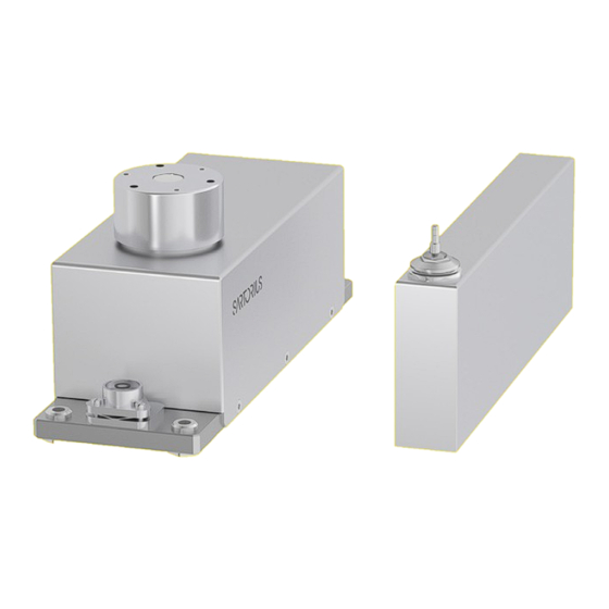
- Page 9 Device Description Fig. 3: WZB25-NC—View from the front (left) and rear (right) Pos . Name Description Pressure outlet For pressure inlet 1 and pressure inlet 2 Rinsing run air outlet — Rinsing run air outlet < 50 mbar — D = 6 mm Pressure inlet 1 — For closing mechanism —...
-
Page 10: Electronics Unit
Device Description 3.1.2 Electronics Unit Fig. 4: Electronics unit Pos . Name Description Electronics Unit DC jack Female connector, weigh cell USB-C connection — Is screw-on. — For the YRD01 display unit Indicator light TxD and RxD Flashes yellow during data transfer. Power indicator light —... -
Page 11: Operating Design
Operating Design Operating Design CAS Suite User Interface Fig. 5: CAS Suite menu view Pos . Designation Description Code number — There is a code number for each parameter. — If the number illuminates in green: This parameter is selected. [+ | -] button To open (+) or close (-) a level. -
Page 12: Menu Structure, Main Menu
Operating Design Menu Structure, Main Menu with CAS Suite Navigating in menus with the mouse button. Level 1 Level 2 Description Active setup menu BALANCE Set the functions of the device. General settings Menu reset Active device menu Interface_1 Define the parameters for the COM interface. (RS-232) Interface_2 Define the parameters for the USB interface. -
Page 13: Installation
Installation Installation Scope of Delivery The weigh cells can be supplied in various designs. If Article Quantity options (special equipment) have been ordered, the Weigh cell desired options will be added to the cells in the plant. Electronics unit Operating instructions (this document) NOTICE Power supply unit with country-specific power cord... -
Page 14: Installation Instructions
— Do not expose to extreme moisture. Leveling the Load Receptor for — Do not expose to magnetic influences. User-specific Load Holder (Except for WZB25-NC) Acclimatization Procedure When a cold device is brought into a warm environment: The temperature difference can lead to condensation Apply the spacer from humidity in the device (moisture formation). -
Page 15: Leveling Weigh Cells (Leveling Feet Optional)
Installation Securely Installing Weigh Cells If required: Screw the user-specific load holder onto the thread Requirement (5) of the load receptor (for torques, see The installation of the weigh cell is complete. Chapter “5.11 Procedure Maximum Load on the Pan Support”, page 16). -
Page 16: Maximum Load On The Pan Support
Installation 5.11 Maximum Load on the Pan Support Fig. 6: Maximum load on the pan support Pos . Name Description Force holding point Model Unit Value Value Value Value Value Maximum torques (Mx. My, Mz) Torque forces Maximum force opposite to direction of load (-F Maximum forces on the force holding point Either the maximum forces or torques may be present. - Page 17 Installation The torque My is the sum of the torque of the weight force MLoad, the torque of any possible excess weight that may be applied MEx and the torque from the net weight MCant of the load holder. The force Fz is made up of the weight force FLoad, the weight force of the cantilever FCant, and the overload force FOver.
-
Page 18: Getting Started
Procedure the device to the power supply. Contact Sartorius Service. Select the country- Only use original Sartorius power supply units. specific power plug adapter. The power plug Insert the right-angle plug of the power supply unit adapter must be suitable into the electronics module and tighten the screw. -
Page 19: System Settings
Handshake regulations applicable in your country. The weigh cell interface SBI (Sartorius Balance The device can be Interface) has transmit and receive buffers. Different operated with a DC handshake modes can be set in the weigh cell menu: voltage of 12 V to... -
Page 20: Data Output Rates - Values Per Second
Remove the screw Adjustment plug (1). Procedure Perform adjustment functions: — Via control commands with Sartorius configuration software CAS Suite installed on a computer (see Chapter “8.6 “Calibration, Adjustment” Function via Interface RS232 (Examples)”, page 38) — With the optional YRD01 display unit... - Page 21 System Settings For the models WZB254-N | -ND | -NC, WZB653-N | WZB1402-N | -NC Carefully screw in the customer-supplied load holder on the M3 thread (2): Observe the maximum screw-in torque of 0.8 Nm. NOTICE The screw-in depth may not exceed 5 mm If required, install a draft protection shield.
-
Page 22: Parameter List
System Settings Parameter List 7.9.1 “Active Setup Menu” Menu Level 1 Level 2 Level 3 Level 4 Codes Active setup Balance Installation site/ambient Very stable conditions 1. 1. 1. 1 menu conditions Stable conditions 1. 1. 1. 2 Unstable conditions 1. - Page 23 System Settings Level 1 Level 2 Level 3 Level 4 Codes Active setup Balance Weight unit Available unit 1. 1. 7. 1 menu g, grams 1. 1. 7. 2 Units: Kilogram to Newton 1. 1. 7. 3 up to 1. 1. 7. 23 Accuracy All digits on 1.
- Page 24 System Settings Level 1 Level 2 Level 3 Level 4 Codes Active setup Balance Tare/zero at power on 1. 1. 13. 1. menu 1. 1. 13. 2. Output rate Normal 1. 1. 14. 1. Fast 1. 1. 14. 2. Slow, typ. 10 Hz 1.
-
Page 25: Active Print Menu" Menu
System Settings 7.9.2 “Active Print Menu” Menu Level 1 Level 2 Level 3 Level 4 Codes Active print Communication Data output Individual value without stability 3. 1. 1. 1 menu parameters Individual value after stability 3. 1. 1. 2 Automatic, without stability 3. -
Page 26: Active Device Menu" Menu
System Settings 7.9.3 “Active Device Menu” Menu Level 1 Level 2 Level 3 Level 4 Codes Active device Interface_ 1 Data protocol 2. 1. 1. 1 menu (RS232) XBPI 2. 1. 1. 2 SBI 2nd display 2. 1. 1. 4 Universal printer (YDP20) 2. - Page 27 System Settings Level 1 Level 2 Level 3 Level 4 Codes Active device Interface_ 2 Data protocol 2. 2. 1. 1 menu (USB) XBPI 2. 2. 1. 2 SBI 2nd display 2. 2. 1. 4 PC spreadsheet format 2. 2. 1. 6 Universal printer (YDP20) 2.
- Page 28 System Settings Level 1 Level 2 Level 3 Level 4 Codes Active device Interface_ 2 Detected* None/printer/virt com. /PC 2. 2. 7. 0. menu (USB) host/input device Additional function Menu Menu can be edited 2. 9. 1. 1 Menu read only 2.
-
Page 29: Active Appl. Menu" Menu
System Settings 7.9.4 “Active Appl. Menu” Menu Level 1 Level 2 Level 3 Level 4 Codes Active appl. Weighing only Unit Toggle 4. 1. 1. 1 menu 4. 1. 1. 2 Counting Resolution Display accuracy 4. 3. 1. 1 4. 3. 1. 2 Reference updating 4. - Page 30 System Settings Level 1 Level 2 Level 3 Level 4 Codes Active appl. Calculation Method Multiplication 4. 8. 1. 1 menu Division 4. 8. 1. 2 Decimal places Without decimal place 4. 8. 1. 1 1 decimal place 4. 8. 1. 2 2 decimal places 4.
-
Page 31: Operation
Operation Operation Aside from purely mechanical solutions (e.g., using a special weighing pan to shield the sample), bombarding the sample with ions of opposing polarity to neutralize the surface charge is one of the most effective methods Notes on “Analytical Weighing” for eliminating static electricity. -
Page 32: Influence Of Drafts
Operation 8.1.4 Influence of Drafts Depending on the size of the load holder and the sample, there may be an influence from drafts. Use an appropriate draft shield to reduce the influence. Protect the weigh cell from drafts. Operation with a Computer The weigh cells are equipped with two data interfaces (RS232 and USB-C), to which a computer or another peripheral device can be connected. - Page 33 Operation Special Outputs Position * Space High: Overload Cal.Ext.: Adjustment, external Low: Underweight Error Message Position * Space ###: Error number ** For cause and solution, please refer to the “Error Codes” section Example: Output of the weight value + 123 .56 g Position Position 1: “+”...
-
Page 34: Output Format With 22 Characters (Compatibility With Current Weigh Cells)
Operation Output Format with 22 Characters (Compatibility with Current Weigh Cells) In this case, a 6-character code precedes the 16-character output format. These six characters identify the subsequent value. K: ID code character E: Measurement unit characters * Space CR: Carriage return A: Displayed characters LF: Line feed Example Special Operation:... -
Page 35: Compatibility With Older Wz/Wza
Operation 8.4.1 Compatibility with Older WZ/WZA Weigh Cells After the command “ESC s9_” is sent, the data input and output behaves as for older Sartorius WZ/WZA weigh cells (previous models). Data Output Format During output, in “SBI” operating mode 16 characters are output. - Page 36 Operation Error Message Position Space Error number Example: Output of the Weight Value + 255 .7 g Position Position 1: “+” sign, “-” sign, or space Position 2: Space Position 3 - 10: Weight value with decimal point; leading zeros are output as spaces Position 11: Space Position 12 - 14:...
-
Page 37: Weigh Cells
Operation Commands (Data Input Format with Compatibility with the Current Weigh Cells) The computer connected via the data interface can send commands to the weigh cell to trigger functions. These commands are control commands and may have various formats. Control commands consist of up to 13 characters. Each of these characters must be sent based on the menu settings for data transmission. -
Page 38: Calibration, Adjustment" Function Via
Output BAC software version (new notation) = Only for balances with internal motor weight unit “Calibration, Adjustment” The WZB25-NC weigh cell has an integrated adjustment weight of approx. 10 g. This can be used to Function via Interface RS232 check the proper function and readjust the sensitivity of (Examples) the weigh cell. -
Page 39: External Adjustment
The display shows 0.0000 g. The display shows Cal.END. The adjustment weight appears: +50.0000 g. Remove the adjustment weight. Model WZB25-NC The display shows 0.0000 g. Requirement — The application SETUP - Balance - CAL./ADJ. - Ext. adjustment with user-defined weight is set up. -
Page 40: Operating Design Of The Optional Yrd01
Operation Operating Design of the 8.7.2 Menu and System Settings Display Optional YRD01 Display Unit 8.7.1 Operating Display in Weighing Mode Fig. 8: Menu and system settings display (example) Pos . Designation Description Menu or Fig. 7: Operating display in weighing mode (example) parameter entry Display Pos . -
Page 41: Buttons
Operation 8.7.3 Buttons Symbol Designation Description [On/Off] button — When the button is pressed: Switches the operating display on. — If the button is held down: Switches the operating display off. [Menu] button — When the button is pressed: The settings menu opens. —... -
Page 42: Displays In The Operating Display
Operation 8.7.4 Displays in the Operating Display Symbol Designation Description [Counting] display Indicates that the “Counting” application is selected. [Percent weighing] Indicates that the “Percent weighing” application is selected. display [Calculation] display Indicates that the “Calculation” application is selected. [Animal weighing] Indicates that the “Animal weighing”... -
Page 43: Menu Structure, Main Menu With The Yrd01 Display Unit
Operation 8.7.5 Menu Structure, Main Menu with the YRD01 Display Unit Navigating the menus (see Chapter “8.7.6 Menu Navigation with YRD01 Display Unit”, page 44). Level 1 Level 2 Description SETUP BALANCE Set the functions of the device. GEN.SERV. Reset the menu to factory settings. “General services”... -
Page 44: Menu Navigation With Yrd01
Operation 8.7.6 Menu Navigation with YRD01 Display Unit Procedure To open the main menu: Press the [Menu] button. To display menu items or parameters of a level: Press the [Up] or [Down] button. To return to the next higher menu level or exit the menu: Press the [Back] button. To open a displayed menu level or a displayed parameter: Press the [Confirm] button. -
Page 45: Switching Yrd01 On And Off
Operation 8.8.1 Switching YRD01 On and Off If the calibration with subsequent automatic adjustment function is selected: The “CAL.RUN.” display appears in the operating Procedure display during the process. CAUTION Pointed or sharp-edged objects may The “CAL.END” display indicates the end of the damage the operating display! adjustment process. -
Page 46: Weighing
Operation The “CAL.END” message indicates the end of the 8.9.2 Deactivating the Weigh Cell adjustment process. Remove the adjustment weight. Procedure If the calibration without subsequent automatic To deactivate the weigh cell: adjustment function is selected and the adjustment weight placed on the device is within the specified —... -
Page 47: Malfunctions
A previously forgotten weight the device is too low. was removed after starting the device. An error exists in the weighing Contact Sartorius Service. system or in the device electronics. COMM.ERR. The device is not No communication exists Wait until the display unit... - Page 48 Changing Setup Configurations Foreign object is caught between Remove the foreign object weighing pan and housing The weight readout Balance not adjusted Adjustment is obviously wrong Not tared before weighing Tare Other error Contact Sartorius Service: http://www.sartorius.com Operating Instructions Weigh Cells...
-
Page 49: Transport
The packaging is made of environmentally friendly ma- well as measures for subsequent cleaning and disinfec- terials that can be used as secondary raw materials. tion of the device or parts by Sartorius are charged to the sender. Procedure Dispose of the device. Follow the disposal instruc- Requirement tions on our website (www.sartorius.com). -
Page 50: Technical Data
13.2.1 Weigh Cell Power Supply Unit Value Input voltage 12–26 Power consumption, max. 13.2.2 Power Supply Unit Unit Value Type: Sartorius power supply unit YEPS01-15V0H Primary Voltage 100–240 (±10%) Frequency 50–60 Current consumption, maximum Secondary Voltage 15 (± 5%) Current, maximum 0.53... -
Page 51: Data Interfaces
Technical Data 13.3 Data Interfaces 13.3.1 Specification of the RS232 Interface Type of interface: Serial interface Interface operation: Full duplex Level: RS 232 Transmission rate: 600...115200 baud Parity: odd, even, none Number of data bits: 7 or 8 bits Character transmission: Start bit, 7-bit ASCII, parity, 1 or 2 stop bits Handshake —... -
Page 52: Acclimatization Before Power Supply
VA (load receptor: AL chem. nickel- WZB1403-N | -NC | WZB8202-N | -NC plated) Electronics Unit Models WZB25-NC | WZB254-N | -ND | -NC | WZB653-N | Aluminum transp. passivated WZB1403-N | -NC | WZB8202-N | -NC Weigh Cell Operating Instructions... -
Page 53: Dimensions (Scale Drawings)
Technical Data 13.8 Dimensions (Scale Drawings) 4 2 . 5 4 3 . 7 2 0 0 1 5 8 . 0 1 2 5 . 9 9 ± 0 . 1 2 2 . 5 ; 7 t i e f / d e e p 1 8 4 5 7 . - Page 54 Technical Data 4 2 . 5 4 3 . 7 2 0 0 1 5 8 ± 0 . 1 2 2 . 5 1 8 4 ; 7 t i e f / d e e p ± 0 . 1 ±...
- Page 55 1 7 9 . 5 - 0 . 0 1 - 0 . 0 2 - 0 . 0 1 2 . 5 - 0 . 0 2 Fig. 12: Dimensions for model WZB25-NC (in mm) Weigh Cell Operating Instructions...
- Page 56 Technical Data 1 9 0 ± 0 . 1 2 2 . 5 2 1 6 8 8 . 5 5 3 x M ; 7 t i e f / d e e p 3 x M 6 9 6 . 5 5 ±...
- Page 57 Technical Data 2 3 2 1 9 0 ± 0 . 1 1 7 . 5 2 1 6 8 8 . 5 ; 7 t i e f / d e e p ± 0 . 1 9 6 . 5 ±...
- Page 58 Technical Data 1 3 0 1 0 5 1 1 8 . 4 Fig. 15: Dimensions for electronics unit (mm) 240.32 ± 0.80 56.94 ± 0.80 201.09 ± 0.60 Fig. 16: Dimensions for optional YRD01 display unit (in mm) Weigh Cell Operating Instructions...
-
Page 59: Metrological Data
Technical Data 13.9 Metrological Data Model Unit Value Value Value Value Value Value Technology Weighing range 1,400 8,200 Readability 0.00001 0.0001 0.0001 0.001 0.001 0.01 Preload on load receptor min. 5 0–50 0–50 0–100 0–100 0–1300 Tare range (subtractive) Over entire weighing range Reproducibility <±g 0.00002... -
Page 60: Accessories
Sartorius Service is available should there be any queries regarding the device. Please visit the Sartorius website (www. sartorius.com) for information about the service addresses, services provided, or to contact a local representative. When contacting Sartorius Service with questions about the system or in the event of malfunctions, be sure to have the device information, e.g., serial number, close at hand. This information can be found on the manufacturer’s ID label. -
Page 61: Conformity Documents
EN IEC 63000:2018 Standard(s) Die Person, die bevollmächtigt ist, die technischen Unterlagen zusammenzustellen: The person authorised to compile the technical file: Sartorius Lab Instruments GmbH & Co. KG Electronics & Product Compliance 37070 Goettingen, Germany Sartorius Lab Instruments GmbH & Co. KG... - Page 62 U U K K D D e e c c l l a a r r a a t t i i o o n n o o f f C C o o n n f f o o r r m m i i t t y y Sartorius Lab Instruments GmbH & Co. KG...
- Page 63 Sartorius Lab Instruments GmbH & Co. KG Otto-Brenner-Strasse 20 37079 Goettingen, Germany Phone: +49 551 308 0 www.sartorius.com The information and figures contained in these instructions correspond to the version date specified below. Sartorius reserves the right to make changes to the technology, features, specifications and design of the equipment without notice.
Need help?
Do you have a question about the WZB25-NC and is the answer not in the manual?
Questions and answers