
Related Manuals for Pickering 40-500


Summary of Contents for Pickering 40-500
- Page 1 40-500 User Manual PXI Solid State Very High Density Matrix Module pickeringtest.com Issue 4.4 November 2021...
- Page 2 © COPYRIGHT (2021) PICKERING INTERFACES. ALL RIGHTS RESERVED. No part of this publication may be reproduced, transmitted, transcribed, translated or stored in any form, or by any means without the written permission of Pickering Interfaces. Technical details contained within this publication are subject to change without notice.
- Page 3 Pickering Interfaces strives to fulfil all relevant environmental laws and regulations and reduce wastes and releases to the environment. Pickering Interfaces aims to design and operate products in a way that protects the environment and the health and safety of its employees, customers and the public. Pickering Interfaces endeavours to develop and manufacture products that can be produced, distributed, used and recycled, or disposed of, in a safe and environmentally friendly manner.
-
Page 4: Product Safety
If this product is heavy reference should be made to the safety instructions for provisions of lifting and moving. STATIC SENSITIVE To indicate that static sensitive devices are present and handling precautions should be followed. REED RELAY MODULE 40-110/115/120/125 SOLID STATE VERY HIGH DENSITY MATRIX 40-500 Page (IV) Page (IV) -
Page 5: Table Of Contents
Module Architecture ..............4.2 Programming The Module ............4.3 Section 5 Connector Information ..............5.1 Section 6 Trouble Shooting .................6.1 Section 7 Maintenance Information ............7.1 Switching System Test Tools ..........7.1 Relay Lookup Tables .............7.1 SOLID STATE VERY HIGH DENSITY MATRIX 40-500 Page (V) - Page 6 THIS PAGE INTENTIONALLY BLANK SOLID STATE VERY HIGH DENSITY MATRIX 40-500 Page (VI)
-
Page 7: Warnings And Cautions
Not to be used in safety critical circuits, refer to the Pickering Interfaces’ terms & conditions of sale. This module must not be used for the switching of Mains Circuits. For the switching of voltages up to the module’s full specification, Secondary Circuit power supplies and the Device Under Test must... - Page 8 • For suitably equipped products in the event of an emergency press the red “emergency stop” button situated on the front of the unit. SOLID STATE VERY HIGH DENSITY MATRIX 40-500 Page (VIII) 2 AMP 1-POLE UHD MATRIX MODULES 40-575 / 576 / 577 / 578 / 579...
-
Page 9: Technical Specification
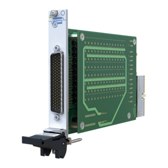
Supported by PXI or LXI Chassis y Supported by eBIRST ™ y 3 Year Warranty The 40-500 is a very high density matrix using solid state switching. It is configured as a 64x4 1-pole matrix and occupies a single PXI slot. - Page 10 3D models for all versions in a variety of popular file formats are available on request. Connectors Side View of the 40-500 Matrix Module PXI bus via 32-bit P1/J1 backplane connector. Signals via front panel 78-pin male D-type connector, for pin outs please refer to the operating manual.
- Page 11 All customized products are given a unique part number, Solutions catalog. fully documented and may be ordered at any time in the Examples of connectors and cabling for the 40-500 are: future. Please contact your local sales office to discuss. 40-960-078...
- Page 12 We provide a full range of supporting cable and connector solutions for all our switching products—20 connector families with 1200+ products. We offer everything from simple mating connectors to complex cables assemblies and terminal blocks. All assemblies are manufactured by Pickering and are guaranteed to mechanically and electrically mate to our modules. Connectors & Backshells...
- Page 13 Solid State VHD Matrix, 40-500 Programming Pickering provide kernel, IVI and VISA (NI & Keysight) drivers which are compatible with all Microsoft supported versions of Windows and popular older versions. For a list of all supporting operating systems, please see: pickeringtest.com/os...
- Page 14 SECTION 1 - TECHNICAL SPECIFICATION pickering THIS PAGE INTENTIONALLY BLANK SOLID STATE VERY HIGH DENSITY MATRIX 40-500 Page 1.6...
-
Page 15: Functional Description
U54, U55, U56, U57, BRIDGE RELAY RELAY CONTROL CONTACTS PRL1-144 +3.3V MODULE CONFIGURATION 2.5 VOLT REGULATOR +2.5V PCI BRIDGE CONFIGURATION Figure 7.1 - Solid State Matrix Module 40-500: Functional Block Diagram SOLID STATE VERY HIGH DENSITY MATRIX 40-500 Page 2.1... - Page 16 SECTION 2 - TECHNICAL DESCRIPTION pickering THIS PAGE INTENTIONALLY BLANK SOLID STATE VERY HIGH DENSITY MATRIX 40-500 Page 2.2...
-
Page 17: Installation
Modular products require installation in a suitable PXI/LXI chassis. The module is designed for indoor use only. PREOPERATION CHECKS (UNPACKING) 1. Check the module for transport damage and report any damage immediately to Pickering Interfaces. Do not attempt to install the product if any damage is evident. -
Page 18: Hardware Installation
For a system comprising more than one chassis, turn ON the last chassis in the system followed by the penultimate, etc, and finally turn ON the external controller or chassis containing the system controller. 9. For Pickering Interfaces modular LXI installation there is no requirement to use any particular power up sequence. -
Page 19: Testing Operation
Figure 3.2 - General Soft Front Panel Icon A selector panel will appear, listing all installed Pickering PCI, PXI or LXI switch cards and resistor cards. Click on the card you wish to control, and a graphical control panel is presented allowing operation of the card. - Page 20 SECTION 3 - INSTALLATION pickering THIS PAGE INTENTIONALLY BLANK SOLID STATE VERY HIGH DENSITY MATRIX 40-500 Page 3.4...
-
Page 21: Programming Guide
SECTION 4 - PROGRAMMING GUIDE PROGRAMMING OPTIONS FOR PICKERING INTERFACES PXI MODULES For information on the installation and use of drivers and the programming of Pickering’s products in various software environments, please refer to the Software User Manual. This is available as a download from: https://www.pickeringtest.com/support/software-drivers-and-downloads... -
Page 22: Module Architecture
MODULE ARCHITECTURE The 40-500 is a single pole switching matrix with 64 connections on the X-axis and 4 connections on the Y-axis. Connections are made by operating the relays at the crosspoints between X and Y lines allowing single X-Y connections, or X-X connections using a Y line as a path. -
Page 23: Programming The Module
Once the drivers are installed the manual “Sys40Prg.pdf” and driver help files which fully describes these functions can be found in the Pickering folder(s) or the Pickering entries on your Start Menu. The card must be opened before use and closed after using the following function calls: Direct I/O Driver - Open with PIL_OpenCards or PIL_OpenSpecifiedCard and close with PIL_CloseCards or PIL_CloseSpecifiedCards respectively. - Page 24 SECTION 4 - PROGRAMMING GUIDE pickering THIS PAGE INTENTIONALLY BLANK SOLID STATE VERY HIGH DENSITY MATRIX 40-500 Page 4.4...
-
Page 25: Connector Information
SECTION 5 - CONNECTOR INFORMATION pickering SECTION 5 - CONNECTOR INFORMATION Figure 5.1 - Pinouts: Solid State Matrix Module 40-500 (78-pin male D-type connector viewed from front of module) SOLID STATE VERY HIGH DENSITY MATRIX 40-500 Page 5.1... - Page 26 SECTION 5 - CONNECTOR INFORMATION pickering THIS PAGE INTENTIONALLY BLANK SOLID STATE VERY HIGH DENSITY MATRIX 40-500 Page 5.2...
-
Page 27: Trouble Shooting
PCI configuration, highlighting any potential configuration problems. Specific details of all installed Pickering switch cards are included. All the installed Pickering switch cards should be listed in the “Pilpxi information” section - if one or more cards is missing it may be possible to determine the reason by referring to the PCI configuration dump contained in the report, but interpretation of this information is far from straightforward, and the best course is to contact Pickering support: support@pickeringtest.com, if possible... - Page 28 SECTION 6 - TROUBLE SHOOTING pickering THIS PAGE INTENTIONALLY BLANK SOLID STATE VERY HIGH DENSITY MATRIX 40-500 Page 6.2...
-
Page 29: Maintenance Information
For PXI modules which are supported in one of Pickering Interfaces’ Modular LXI Chassis (such as the 60-102B and 60-103B) no module software update is required. If the module was introduced after the LXI chassis was manufactured the module may not be recognized, in this case the chassis firmware may need upgrading. - Page 30 RL167 RL211 RL255 RL39 RL83 RL127 RL168 RL212 RL256 RL40 RL84 RL128 RL169 RL213 RL257 RL41 RL85 RL170 RL214 RL42 RL86 RL171 RL215 RL43 RL87 RL172 RL216 RL44 RL88 RL173 RL217 SOLID STATE VERY HIGH DENSITY MATRIX 40-500 Page 7.2...
- Page 31 RL11 RL142 RL130 RL118 RL106 RL94 RL82 RL70 RL58 RL46 RL34 RL22 RL10 RL141 RL129 RL117 RL105 RL93 RL81 RL69 RL57 RL45 RL33 RL21 Figure 7.1 - 40-500 Motherboard Component Layout SOLID STATE VERY HIGH DENSITY MATRIX 40-500 Page 7.3...
- Page 32 SECTION 7 - MAINTENANCE INFORMATION pickering Figure 7.2 - 40-500 Daughterboard Component Layout SOLID STATE VERY HIGH DENSITY MATRIX 40-500 Page 7.4...
Need help?
Do you have a question about the 40-500 and is the answer not in the manual?
Questions and answers