
Related Manuals for Pickering 40-559


Summary of Contents for Pickering 40-559
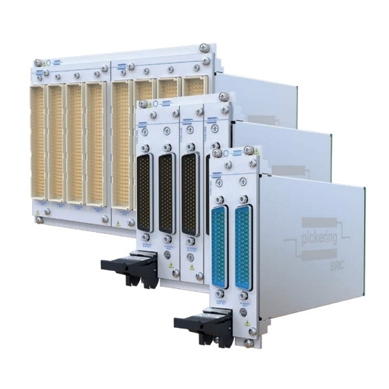
- Page 1 40-559 User Manual PXI BRIC™ Multi-Slot Ultra High Density Matrix Module pickeringtest.com Issue 1.9 August 2022...
- Page 2 © COPYRIGHT (2022) PICKERING INTERFACES. ALL RIGHTS RESERVED. No part of this publication may be reproduced, transmitted, transcribed, translated or stored in any form, or by any means without the written permission of Pickering Interfaces. Technical details contained within this publication are subject to change without notice.
- Page 3 Pickering Interfaces strives to fulfil all relevant environmental laws and regulations and reduce wastes and releases to the environment. Pickering Interfaces aims to design and operate products in a way that protects the environment and the health and safety of its employees, customers and the public. Pickering Interfaces endeavours to develop and manufacture products that can be produced, distributed, used and recycled, or disposed of, in a safe and environmentally friendly manner.
-
Page 4: Product Safety
If this product is heavy reference should be made to the safety instructions for provisions of lifting and moving. STATIC SENSITIVE To indicate that static sensitive devices are present and handling precautions should be followed. REED RELAY MODULE 40-110/115/120/125 PXI BRIC MULTI-SLOT ULTRA HIGH DENSITY MATRIX (40-559) Page (IV) Page (IV) -
Page 5: Table Of Contents
Maintenance Information ............7.1 Switching System Test Tools ..........7.1 Fuse Replacement ..............7.1 Relay Look-Up Tables ............7.2 PCB Layout Diagrams ............7.11 Card Removal From BRIC............. 7.13 Card Replacement ..............7.15 PXI BRIC MULTI-SLOT ULTRA HIGH DENSITY MATRIX (40-559) Page (V) - Page 6 THIS PAGE INTENTIONALLY BLANK PXI BRIC MULTI-SLOT ULTRA HIGH DENSITY MATRIX (40-559) Page (VI)
-
Page 7: Warnings And Cautions
Not to be used in safety critical circuits, refer to the Pickering Interfaces’ terms & conditions of sale. This module must not be used for the switching of Mains Circuits. For the switching of voltages up to the module’s full specification, Secondary Circuit power supplies and the Device Under Test must... - Page 8 • For suitably equipped products in the event of an emergency press the red “emergency stop” button situated on the front of the unit. 2 AMP 1-POLE UHD MATRIX MODULES 40-575 / 576 / 577 / 578 / 579 PXI BRIC MULTI-SLOT ULTRA HIGH DENSITY MATRIX (40-559) Page (VIII) Page (VIII)
-
Page 9: Technical Specification
For more information go to: pickeringtest.com/ebirst X1024 The 40-559 BRIC Module is available with matrix sizes between 64x16 and 1024x4 pickeringtest.com PXI BRIC MULTI-SLOT ULTRA HIGH DENSITY MATRIX (40-559) Page 1.1... - Page 10 Up to 192x8 Reed relay switching solutions can only be as good as the BRIC8 Up to 384x8 relays used, and Pickering uses only the highest quality 40-565B - 2-Pole Matrix, 2A Electro-mechanical Relay instrumentation grade reed relays manufactured by our BRIC2 Up to 58x8 Relay Division.
- Page 11 Y Connections - A Analog Bus B Y Connections - B x8 Configurations Architecture diagrams for x4, x6 and x8 configurations of the 40-559 range showing how the matrix daughter cards are interconnected with either quad or dual analog buses. Isolation Switches...
- Page 12 Analog Bus Y Connections x16 Configurations Architecture diagrams for x12 and x16 configurations of the 40-559 range showing how the matrix daughter cards are interconnected with a single analog bus. Analog Bus The Y-buses of the 40-559 daughter cards are linked via the analog bus on the BRIC backplane.
- Page 13 BRIC Ultra High Density Matrix, 40-559 Pickering Electronics Maximum Crosspoint Count State-Of-The-Art Reed Relays The 40-559 series has a suggested maximum number of This matrix module is constructed simultaneously operated crosspoints of 50 per BRIC2, 50 using Series 120 Reed Relays per BRIC4 or 100 per BRIC8 (please contact factory for manufactured by our Relay Division.
- Page 14 For further assistance, please contact the sales office. 96x16 Matrix -96x16 -96x16 128x16 Matrix -128x16 -128x16 Mating Connectors & Cabling 160x16 Matrix -160x16 For connection accessories for the 40-559 module please 192x16 Matrix -192x16 refer to the 90-001D 160-pin DIN 41612, 90-022D 104-pin 224x16 Matrix -224x16...
- Page 15 We provide a full range of supporting cable and connector solutions for all our switching products—20 connector families with 1200+ products. We offer everything from simple mating connectors to complex cables assemblies and terminal blocks. All assemblies are manufactured by Pickering and are guaranteed to mechanically and electrically mate to our modules. Connectors & Backshells...
- Page 16 BRIC Ultra High Density Matrix, 40-559 Programming Pickering provide kernel, IVI and VISA (NI & Keysight) drivers which are compatible with all Microsoft supported versions of Windows and popular older versions. For a list of all supporting operating systems, please see: pickeringtest.com/os...
-
Page 17: Technical Description
The backplane provides mounting for the 36-pin connectors (into which the Sub-Matrix Cards plug) and Control logic. Figure 2.1 - Fully Populated 40-559 BRIC8 Matrix Module (x4 Configuration) FUNCTIONAL DESCRIPTION A functional block diagram is provided in Figure 2.2. The BRIC Module is powered by a +5V input via Compact PCI connector J1 mounted on the Backplane. - Page 18 Y Bus C Relays Y Bus D Slot 1 Relay Matrix Coils EEPROM X Bus Relay Drivers U2 to U67 Figure 2.2 - 40-559 BRIC Module x4 Configuration: Functional Block Diagram PXI BRIC MULTI-SLOT ULTRA HIGH DENSITY MATRIX (40-559) Page 2.2...
- Page 19 Y Isolation Y Bus B Relays Relay Slot 1 Matrix Coils EEPROM X Bus Relay Drivers U2 to U67 Figure 2.3 - 40-559 BRIC Module x8 Configuration: Functional Block Diagram PXI BRIC MULTI-SLOT ULTRA HIGH DENSITY MATRIX (40-559) Page 2.3...
- Page 20 Analog Bus B is only Coils applicable to x6 EEPROM X Bus configurations Relay Drivers U2 to U67 Figure 2.4 - 40-559 BRIC Module x6, x12 & x16 Configurations: Functional Block Diagram PXI BRIC MULTI-SLOT ULTRA HIGH DENSITY MATRIX (40-559) Page 2.4...
- Page 21 X129 X256 MATRIX CARD 2 Isolation Switches Front Panel 160-pin DIN 41612 Connector X897 X1024 MATRIX CARD 8 Isolation Switches Figure 2.5 - 40-559 BRIC Module: x4 Configuration Switching Architecture PXI BRIC MULTI-SLOT ULTRA HIGH DENSITY MATRIX (40-559) Page 2.5...
- Page 22 Front Panel 104-pin D-type Connector X168 Isolation Switches MATRIX CARD 2 Front Panel 104-pin D-type Connector X589 X672 Isolation Switches MATRIX CARD 8 Figure 2.6 - 40-559 BRIC Module: x6 Configuration Switching Architecture PXI BRIC MULTI-SLOT ULTRA HIGH DENSITY MATRIX (40-559) Page 2.6...
- Page 23 Front Panel 78-pin D-type Connector X128 Isolation MATRIX CARD 2 Switches Front Panel 78-pin D-type Connector X449 X512 Isolation MATRIX CARD 8 Switches Figure 2.7 - 40-559 BRIC Module: x8 Configuration Switching Architecture PXI BRIC MULTI-SLOT ULTRA HIGH DENSITY MATRIX (40-559) Page 2.7...
- Page 24 Front Panel 78-pin D-type Connector Isolation Switches MATRIX CARD 2 Front Panel 78-pin D-type Connector X295 X336 Isolation Switches MATRIX CARD 8 Figure 2.8 - 40-559 BRIC Module: x12 Configuration Switching Architecture PXI BRIC MULTI-SLOT ULTRA HIGH DENSITY MATRIX (40-559) Page 2.8...
- Page 25 Front Panel 78-pin D-type Connector Isolation Switches MATRIX CARD 2 Front Panel 78-pin D-type Connector X225 X256 Isolation Switches MATRIX CARD 8 Figure 2.9 - 40-559 BRIC Module: x16 Configuration Switching Architecture PXI BRIC MULTI-SLOT ULTRA HIGH DENSITY MATRIX (40-559) Page 2.9...
- Page 26 SECTION 2 - TECHNICAL DESCRIPTION pickering THIS PAGE INTENTIONALLY BLANK PXI BRIC MULTI-SLOT ULTRA HIGH DENSITY MATRIX (40-559) Page 2.10...
-
Page 27: Installation
Modular products require installation in a suitable PXI/LXI chassis. The module is designed for indoor use only. PREOPERATION CHECKS (UNPACKING) 1. Check the module for transport damage and report any damage immediately to Pickering Interfaces. Do not attempt to install the product if any damage is evident. -
Page 28: Hardware Installation
For a system comprising more than one chassis, turn ON the last chassis in the system followed by the penultimate, etc, and finally turn ON the external controller or chassis containing the system controller. 9. For Pickering Interfaces modular LXI installation there is no requirement to use any particular power up sequence. -
Page 29: Testing Operation
Figure 3.2 - General Soft Front Panel Icon A selector panel will appear, listing all installed Pickering PCI, PXI or LXI switch cards and resistor cards. Click on the card you wish to control, and a graphical control panel is presented allowing operation of the card. - Page 30 SECTION 3 - INSTALLATION pickering THIS PAGE INTENTIONALLY BLANK PXI BRIC MULTI-SLOT ULTRA HIGH DENSITY MATRIX (40-559) Page 3.4...
-
Page 31: Programming Guide
SECTION 4 - PROGRAMMING PROGRAMMING OPTIONS FOR PICKERING INTERFACES PXI MODULES For information on the installation and use of drivers and the programming of Pickering’s products in various software environments, please refer to the Software User Manual. This is available as a download from: https://www.pickeringtest.com/support/software-drivers-and-downloads... -
Page 32: Module Architecture
The 40-559 is a high density 1-pole switching matrix constructed from 128x4, 84x6, 64x8, 42x12 or 32x16 sub- matrix cards linked with an analog backplane. The 40-559 module can be fitted with 1 or 2 sub-matrix cards (BRIC2), between 1 & 4 sub-matrix cards (BRIC4) or between 1 & 8 sub-matrix cards (BRIC8). Connections are made by operating crosspoint relays between X and Y lines allowing single X-Y connections, or X-X connections using a Y line as a path. -
Page 33: Programming The Matrix
PROGRAMMING THE MATRIX For all configurations of the 40-559, the entire matrix is treated as a single programming sub-unit designated as Sub-Unit 1, and the isolation switches of all sub-matrix cards are contained in a single sub-unit designated as Sub-Unit 2 for analog bus A and Sub-Unit 3 for analog bus B and so on. - Page 34 ViUInt32 sub_unit = 1; //Matrix pipx40_setCrosspointState (vi, sub_unit, 3, 2, VI_OFF); //Release x2, y3 ViUInt32 sub_unit = 2; //Backplane Isolation Switches pipx40_setChannelState(vi, sub_unit, 3, VI_OFF); //Disconnect y3 from backplane a PXI BRIC MULTI-SLOT ULTRA HIGH DENSITY MATRIX (40-559) Page 4.4...
- Page 35 Bit 32 Sub-unit 5 Backplane Isolation D Bit 29 Bit 30 Bit 31 Bit 32 MATRIX CARD 8 Figure 4.2 - 40-559 Matrix Module (4-Wire Y-Bus Version) - Sub-unit Allocations PXI BRIC MULTI-SLOT ULTRA HIGH DENSITY MATRIX (40-559) Page 4.5...
- Page 36 Bit 44 Bit 45 Bit 46 Bit 47 Bit 48 Sub-unit 3 Backplane MATRIX CARD 8 Isolation B Figure 4.3 - 40-559 Matrix Module (6-Wire Y-Bus Version) - Sub-unit Allocations PXI BRIC MULTI-SLOT ULTRA HIGH DENSITY MATRIX (40-559) Page 4.6...
-
Page 37: Analog Ya1 Ya8
Bit 60 Bit 65 Bit 64 Bit 63 Bit 64 MATRIX CARD 8 Sub-unit 3 Backplane Isolation B Figure 4.4 - 40-559 Matrix Module (8-Wire Y-Bus Version) - Sub-unit Allocations PXI BRIC MULTI-SLOT ULTRA HIGH DENSITY MATRIX (40-559) Page 4.7... - Page 38 (Backplane Isolation Switches are Set Automatically) ANALOG BACKPLANE MATRIX CARD 1 MATRIX CARD 2 X295 X336 MATRIX CARD 8 Figure 4.5 - 40-559 Matrix Module (12-Wire Y-Bus Version) - Sub-unit Allocations PXI BRIC MULTI-SLOT ULTRA HIGH DENSITY MATRIX (40-559) Page 4.8...
- Page 39 (Backplane Isolation Switches are Set Automatically) ANALOG BACKPLANE MATRIX CARD 1 MATRIX CARD 2 X225 X256 MATRIX CARD 8 Figure 4.6 - 40-559 Matrix Module (16-Wire Y-Bus Version) - Sub-unit Allocations PXI BRIC MULTI-SLOT ULTRA HIGH DENSITY MATRIX (40-559) Page 4.9...
- Page 40 SECTION 4 - PROGRAMMING GUIDE pickering THIS PAGE INTENTIONALLY BLANK PXI BRIC MULTI-SLOT ULTRA HIGH DENSITY MATRIX (40-559) Page 4.10...
- Page 41 65 to 96 Figure 5.35 97 to 128 Figure 5.36 50-pin D-type 129 to 160 Figure 5.37 161 to 192 Figure 5.38 193 to 224 Figure 5.39 225 to 256 Figure 5.40 PXI BRIC MULTI-SLOT ULTRA HIGH DENSITY MATRIX (40-559) Page 5.1...
-
Page 42: Matrix Card
FP_GND FP_GND FP_GND FP_GND FP_GND FP_GND FP_GND FP_GND FP_GND FP_GND 160-pin Male DIN 41612 Connector FP_GND (viewed from front of module) Figure 5.1 - 40-559 128x4 Matrix Card 1 Pinout PXI BRIC MULTI-SLOT ULTRA HIGH DENSITY MATRIX (40-559) Page 5.2... - Page 43 FP_GND FP_GND FP_GND FP_GND FP_GND FP_GND FP_GND FP_GND FP_GND FP_GND 160-pin Male DIN 41612 Connector FP_GND (viewed from front of module) Figure 5.2 - 40-559 128x4 Matrix Card 2 Pinout PXI BRIC MULTI-SLOT ULTRA HIGH DENSITY MATRIX (40-559) Page 5.3...
- Page 44 FP_GND FP_GND FP_GND FP_GND FP_GND FP_GND FP_GND FP_GND FP_GND FP_GND 160-pin Male DIN 41612 Connector FP_GND (viewed from front of module) Figure 5.3 - 40-559 128x4 Matrix Card 3 Pinout PXI BRIC MULTI-SLOT ULTRA HIGH DENSITY MATRIX (40-559) Page 5.4...
- Page 45 FP_GND FP_GND FP_GND FP_GND FP_GND FP_GND FP_GND FP_GND FP_GND FP_GND 160-pin Male DIN 41612 Connector FP_GND (viewed from front of module) Figure 5.4 - 40-559 128x4 Matrix Card 4 Pinout PXI BRIC MULTI-SLOT ULTRA HIGH DENSITY MATRIX (40-559) Page 5.5...
- Page 46 FP_GND FP_GND FP_GND FP_GND FP_GND FP_GND FP_GND FP_GND FP_GND FP_GND 160-pin Male DIN 41612 Connector FP_GND (viewed from front of module) Figure 5.5 - 40-559 128x4 Matrix Card 5 Pinout PXI BRIC MULTI-SLOT ULTRA HIGH DENSITY MATRIX (40-559) Page 5.6...
- Page 47 FP_GND FP_GND FP_GND FP_GND FP_GND FP_GND FP_GND FP_GND FP_GND FP_GND 160-pin Male DIN 41612 Connector FP_GND (viewed from front of module) Figure 5.6 - 40-559 128x4 Matrix Card 6 Pinout PXI BRIC MULTI-SLOT ULTRA HIGH DENSITY MATRIX (40-559) Page 5.7...
- Page 48 FP_GND FP_GND FP_GND FP_GND FP_GND FP_GND FP_GND FP_GND FP_GND FP_GND 160-pin Male DIN 41612 Connector FP_GND (viewed from front of module) Figure 5.7 - 40-559 128x4 Matrix Card 7 Pinout PXI BRIC MULTI-SLOT ULTRA HIGH DENSITY MATRIX (40-559) Page 5.8...
- Page 49 FP_GND FP_GND FP_GND FP_GND FP_GND FP_GND FP_GND FP_GND FP_GND FP_GND 160-pin Male DIN 41612 Connector FP_GND (viewed from front of module) Figure 5.8 - 40-559 128x4 Matrix Card 8 Pinout PXI BRIC MULTI-SLOT ULTRA HIGH DENSITY MATRIX (40-559) Page 5.9...
- Page 50 SECTION 5 - CONNECTOR INFORMATION pickering MATRIX CARD 1 PINOUT FP_GND FP_GND FP_GND Figure 5.9 - 40-559 84x6 Matrix Card 1 Pinout 104-pin Male D-Type Connector (viewed from front of module) MATRIX CARD 2 PINOUT X101 X103 X104 X102 X100...
- Page 51 X248 X246 X244 X252 X250 X251 X249 FP_GND FP_GND FP_GND Figure 5.11 - 40-559 84x6 Matrix Card 3 Pinout 104-pin Male D-Type Connector (viewed from front of module) MATRIX CARD 4 PINOUT X256 X254 X257 X255 X253 X259 X261 X262...
- Page 52 X416 X414 X412 X420 X418 X419 X417 FP_GND FP_GND FP_GND Figure 5.13 - 40-559 84x6 Matrix Card 5 Pinout 104-pin Male D-Type Connector (viewed from front of module) MATRIX CARD 6 PINOUT X424 X422 X425 X423 X421 X427 X429 X430...
- Page 53 X584 X582 X580 X588 X586 X587 X585 FP_GND FP_GND FP_GND Figure 5.15 - 40-559 84x6 Matrix Card 7 Pinout 104-pin Male D-Type Connector (viewed from front of module) MATRIX CARD 8 PINOUT X592 X590 X593 X591 X589 X595 X597 X598...
- Page 54 X126 FP_GND FP_GND FP_GND FP_GND Figure 5.17 - 40-559 64x8 Matrix Card 1 Pinout Figure 5.18 - 40-559 64x8 Matrix Card 2 Pinout 78-pin Male D-Type Connector 78-pin Male D-Type Connector (viewed from front of module) (viewed from front of module)
- Page 55 X384 FP_GND FP_GND FP_GND FP_GND Figure 5.21 - 40-559 64x8 Matrix Card 5 Pinout Figure 5.22 - 40-559 64x8 Matrix Card 6 Pinout 78-pin Male D-Type Connector 78-pin Male D-Type Connector (viewed from front of module) (viewed from front of module)
- Page 56 FP_GND FP_GND FP_GND FP_GND Figure 5.25 - 40-559 42x12 Matrix Card 1 Pinout Figure 5.26 - 40-559 42x12 Matrix Card 2 Pinout 78-pin Male D-Type Connector 78-pin Male D-Type Connector (viewed from front of module) (viewed from front of module)
- Page 57 X251 FP_GND FP_GND FP_GND FP_GND Figure 5.29 - 40-559 42x12 Matrix Card 5 Pinout Figure 5.30 - 40-559 42x12 Matrix Card 6 Pinout 78-pin Male D-Type Connector 78-pin Male D-Type Connector (viewed from front of module) (viewed from front of module)
- Page 58 SECTION 5 - CONNECTOR INFORMATION pickering FP_GND FP_GND Figure 5.33 - 40-559 32x16 Matrix Card 1 Pinout Figure 5.34 - 40-559 32x16 Matrix Card 2 Pinout 50-pin Male D-Type Connector 50-pin Male D-Type Connector (viewed from front of module) (viewed from front of module)
- Page 59 X191 X160 X192 FP_GND FP_GND Figure 5.37 - 40-559 32x16 Matrix Card 5 Pinout Figure 5.38 - 40-559 32x16 Matrix Card 6 Pinout 50-pin Male D-Type Connector 50-pin Male D-Type Connector (viewed from front of module) (viewed from front of module)
- Page 60 SECTION 5 - CONNECTOR INFORMATION pickering THIS PAGE INTENTIONALLY BLANK PXI BRIC MULTI-SLOT ULTRA HIGH DENSITY MATRIX (40-559) Page 5.20...
-
Page 61: Trouble Shooting
PCI configuration, highlighting any potential configuration problems. Specific details of all installed Pickering switch cards are included. All the installed Pickering switch cards should be listed in the “Pilpxi information” section - if one or more cards is missing it may be possible to determine the reason by referring to the PCI configuration dump contained in the report, but interpretation of this information is far from straightforward, and the best course is to contact Pickering support: support@pickeringtest.com, if possible... - Page 62 SECTION 6 - TROUBLE SHOOTING pickering THIS PAGE INTENTIONALLY BLANK PXI BRIC MULTI-SLOT ULTRA HIGH DENSITY MATRIX (40-559) Page 6.2...
-
Page 63: Maintenance Information
The Pickering Interfaces BIRST (Built-In Relay Self Test) Tool provides a simple means of testing selected Pickering Interfaces switching products, including this model. The tool can be used to find relay faults or to provide confirmation that a product is operating correctly, either as part of the regular system calibration or because a system fault is suspected and the switch system needs to be eliminated from the fault finding procedure. - Page 64 Replacement of relays should only be carried out by qualified personnel using the correct equipment. If qualified personnel are not available, or the location of a defective relay cannot be positively determined it is recommended that the module is returned to Pickering Interfaces or a replacement daughter card is ordered.
- Page 65 1 160 128 1 1 385 64 2 1 192 128 2 1 417 64 3 1 224 128 3 1 449 64 4 1 256 128 4 1 481 PXI BRIC MULTI-SLOT ULTRA HIGH DENSITY MATRIX (40-559) Page 7.3...
- Page 66 2 160 256 1 2 385 192 2 2 192 256 2 2 417 192 3 2 224 256 3 2 449 192 4 2 256 256 4 2 481 PXI BRIC MULTI-SLOT ULTRA HIGH DENSITY MATRIX (40-559) Page 7.4...
- Page 67 3 160 384 1 3 385 320 2 3 192 384 2 3 417 320 3 3 224 384 3 3 449 320 4 3 256 384 4 3 481 PXI BRIC MULTI-SLOT ULTRA HIGH DENSITY MATRIX (40-559) Page 7.5...
- Page 68 4 160 512 1 4 385 448 2 4 192 512 2 4 417 448 3 4 224 512 3 4 449 448 4 4 256 512 4 4 481 PXI BRIC MULTI-SLOT ULTRA HIGH DENSITY MATRIX (40-559) Page 7.6...
- Page 69 5 160 640 1 5 385 576 2 5 192 640 2 5 417 576 3 5 224 640 3 5 449 576 4 5 256 640 4 5 481 PXI BRIC MULTI-SLOT ULTRA HIGH DENSITY MATRIX (40-559) Page 7.7...
- Page 70 6 160 768 1 6 385 704 2 6 192 768 2 6 417 704 3 6 224 768 3 6 449 704 4 6 256 768 4 6 481 PXI BRIC MULTI-SLOT ULTRA HIGH DENSITY MATRIX (40-559) Page 7.8...
- Page 71 7 160 896 1 7 385 832 2 7 192 896 2 7 417 832 3 7 224 896 3 7 449 832 4 7 256 896 4 7 481 PXI BRIC MULTI-SLOT ULTRA HIGH DENSITY MATRIX (40-559) Page 7.9...
- Page 72 8 160 1024 1 8 385 960 2 8 192 1024 2 8 417 960 3 8 224 1024 3 8 449 960 4 8 256 1024 4 8 481 PXI BRIC MULTI-SLOT ULTRA HIGH DENSITY MATRIX (40-559) Page 7.10...
- Page 73 SECTION 7 - MAINTENANCE INFORMATION pickering Figure 7.1 - 40-559 128x4 Matrix Card: Component Layout PXI BRIC MULTI-SLOT ULTRA HIGH DENSITY MATRIX (40-559) Page 7.11...
- Page 74 1 342 42 2 1 252 21 3 1 85 84 3 1 385 63 4 1 438 42 5 1 221 21 6 1 181 84 6 1 481 PXI BRIC MULTI-SLOT ULTRA HIGH DENSITY MATRIX (40-559) Page 7.12...
- Page 75 2 342 126 2 2 252 105 3 2 85 168 3 2 385 147 4 2 438 126 5 2 221 105 6 2 181 168 6 2 481 PXI BRIC MULTI-SLOT ULTRA HIGH DENSITY MATRIX (40-559) Page 7.13...
- Page 76 3 342 210 2 3 252 189 3 3 85 252 3 3 385 231 4 3 438 210 5 3 221 189 6 3 181 252 6 3 481 PXI BRIC MULTI-SLOT ULTRA HIGH DENSITY MATRIX (40-559) Page 7.14...
- Page 77 4 342 294 2 4 252 273 3 4 85 336 3 4 385 315 4 4 438 294 5 4 221 273 6 4 181 336 6 4 481 PXI BRIC MULTI-SLOT ULTRA HIGH DENSITY MATRIX (40-559) Page 7.15...
- Page 78 5 342 378 2 5 252 357 3 5 85 420 3 5 385 399 4 5 438 378 5 5 221 357 6 5 181 420 6 5 481 PXI BRIC MULTI-SLOT ULTRA HIGH DENSITY MATRIX (40-559) Page 7.16...
- Page 79 6 342 462 2 6 252 441 3 6 85 504 3 6 385 483 4 6 438 462 5 6 221 441 6 6 181 504 6 6 481 PXI BRIC MULTI-SLOT ULTRA HIGH DENSITY MATRIX (40-559) Page 7.17...
- Page 80 7 342 546 2 7 252 525 3 7 85 588 3 7 385 567 4 7 438 546 5 7 221 525 6 7 181 588 6 7 481 PXI BRIC MULTI-SLOT ULTRA HIGH DENSITY MATRIX (40-559) Page 7.18...
- Page 81 8 342 630 2 8 252 609 3 8 85 672 3 8 385 651 4 8 438 630 5 8 221 609 6 8 181 672 6 8 481 PXI BRIC MULTI-SLOT ULTRA HIGH DENSITY MATRIX (40-559) Page 7.19...
- Page 82 SECTION 7 - MAINTENANCE INFORMATION pickering Figure 7.2 - 40-559 84x6 Matrix Card: Component Layout PXI BRIC MULTI-SLOT ULTRA HIGH DENSITY MATRIX (40-559) Page 7.20...
- Page 83 1 257 64 2 1 289 64 3 1 321 64 4 1 353 64 5 1 385 64 6 1 417 64 7 1 449 64 8 1 481 PXI BRIC MULTI-SLOT ULTRA HIGH DENSITY MATRIX (40-559) Page 7.21...
- Page 84 2 257 128 2 2 289 128 3 2 321 128 4 2 353 128 5 2 385 128 6 2 417 128 7 2 449 128 8 2 481 PXI BRIC MULTI-SLOT ULTRA HIGH DENSITY MATRIX (40-559) Page 7.22...
- Page 85 3 257 192 2 3 289 192 3 3 321 192 4 3 353 192 5 3 385 192 6 3 417 192 7 3 449 192 8 3 481 PXI BRIC MULTI-SLOT ULTRA HIGH DENSITY MATRIX (40-559) Page 7.23...
- Page 86 4 257 256 2 4 289 256 3 4 321 256 4 4 353 256 5 4 385 256 6 4 417 256 7 4 449 256 8 4 481 PXI BRIC MULTI-SLOT ULTRA HIGH DENSITY MATRIX (40-559) Page 7.24...
- Page 87 5 257 320 2 5 289 320 3 5 321 320 4 5 353 320 5 5 385 320 6 5 417 320 7 5 449 320 8 5 481 PXI BRIC MULTI-SLOT ULTRA HIGH DENSITY MATRIX (40-559) Page 7.25...
- Page 88 6 257 384 2 6 289 384 3 6 321 384 4 6 353 384 5 6 385 384 6 6 417 384 7 6 449 384 8 6 481 PXI BRIC MULTI-SLOT ULTRA HIGH DENSITY MATRIX (40-559) Page 7.26...
- Page 89 7 257 448 2 7 289 448 3 7 321 448 4 7 353 448 5 7 385 448 6 7 417 448 7 7 449 448 8 7 481 PXI BRIC MULTI-SLOT ULTRA HIGH DENSITY MATRIX (40-559) Page 7.27...
- Page 90 8 257 512 2 8 289 512 3 8 321 512 4 8 353 512 5 8 385 512 6 8 417 512 7 8 449 512 8 8 481 PXI BRIC MULTI-SLOT ULTRA HIGH DENSITY MATRIX (40-559) Page 7.28...
- Page 91 SECTION 7 - MAINTENANCE INFORMATION pickering Figure 7.3 - 40-559 64x8 Matrix Card: Component Layout PXI BRIC MULTI-SLOT ULTRA HIGH DENSITY MATRIX (40-559) Page 7.29...
- Page 92 1 63 42 3 1 321 21 5 1 159 42 6 1 417 21 8 1 255 42 9 1 258 21 11 1 96 42 12 1 354 PXI BRIC MULTI-SLOT ULTRA HIGH DENSITY MATRIX (40-559) Page 7.30...
- Page 93 2 63 84 3 2 321 63 5 2 159 84 6 2 417 63 8 2 255 84 9 2 258 63 11 2 96 84 12 2 354 PXI BRIC MULTI-SLOT ULTRA HIGH DENSITY MATRIX (40-559) Page 7.31...
- Page 94 3 63 126 3 3 321 105 5 3 159 126 6 3 417 105 8 3 255 126 9 3 258 105 11 3 96 126 12 3 354 PXI BRIC MULTI-SLOT ULTRA HIGH DENSITY MATRIX (40-559) Page 7.32...
- Page 95 4 63 168 3 4 321 147 5 4 159 168 6 4 417 147 8 4 255 168 9 4 258 147 11 4 96 168 12 4 354 PXI BRIC MULTI-SLOT ULTRA HIGH DENSITY MATRIX (40-559) Page 7.33...
- Page 96 5 63 210 3 5 321 189 5 5 159 210 6 5 417 189 8 5 255 210 9 5 258 189 11 5 96 210 12 5 354 PXI BRIC MULTI-SLOT ULTRA HIGH DENSITY MATRIX (40-559) Page 7.34...
- Page 97 6 63 252 3 6 321 231 5 6 159 252 6 6 417 231 8 6 255 252 9 6 258 231 11 6 96 252 12 6 354 PXI BRIC MULTI-SLOT ULTRA HIGH DENSITY MATRIX (40-559) Page 7.35...
- Page 98 7 63 294 3 7 321 273 5 7 159 294 6 7 417 273 8 7 255 294 9 7 258 273 11 7 96 294 12 7 354 PXI BRIC MULTI-SLOT ULTRA HIGH DENSITY MATRIX (40-559) Page 7.36...
- Page 99 8 63 336 3 8 321 315 5 8 159 336 6 8 417 315 8 8 255 336 9 8 258 315 11 8 96 336 12 8 354 PXI BRIC MULTI-SLOT ULTRA HIGH DENSITY MATRIX (40-559) Page 7.37...
- Page 100 SECTION 7 - MAINTENANCE INFORMATION pickering Figure 7.4 - 40-559 42x12 Matrix Card: Component Layout PXI BRIC MULTI-SLOT ULTRA HIGH DENSITY MATRIX (40-559) Page 7.38...
- Page 101 1 289 32 4 1 353 32 6 1 417 32 8 1 481 32 10 1 290 32 12 1 354 32 14 1 418 32 16 1 482 PXI BRIC MULTI-SLOT ULTRA HIGH DENSITY MATRIX (40-559) Page 7.39...
- Page 102 2 289 64 4 2 353 64 6 2 417 64 8 2 481 64 10 2 290 64 12 2 354 64 14 2 418 64 16 2 482 PXI BRIC MULTI-SLOT ULTRA HIGH DENSITY MATRIX (40-559) Page 7.40...
- Page 103 3 289 96 4 3 353 96 6 3 417 96 8 3 481 96 10 3 290 96 12 3 354 96 14 3 418 96 16 3 482 PXI BRIC MULTI-SLOT ULTRA HIGH DENSITY MATRIX (40-559) Page 7.41...
- Page 104 4 289 128 4 4 353 128 6 4 417 128 8 4 481 128 10 4 290 128 12 4 354 128 14 4 418 128 16 4 482 PXI BRIC MULTI-SLOT ULTRA HIGH DENSITY MATRIX (40-559) Page 7.42...
- Page 105 5 289 160 4 5 353 160 6 5 417 160 8 5 481 160 10 5 290 160 12 5 354 160 14 5 418 160 16 5 482 PXI BRIC MULTI-SLOT ULTRA HIGH DENSITY MATRIX (40-559) Page 7.43...
- Page 106 6 289 192 4 6 353 192 6 6 417 192 8 6 481 192 10 6 290 192 12 6 354 192 14 6 418 192 16 6 482 PXI BRIC MULTI-SLOT ULTRA HIGH DENSITY MATRIX (40-559) Page 7.44...
- Page 107 7 289 224 4 7 353 224 6 7 417 224 8 7 481 224 10 7 290 224 12 7 354 224 14 7 418 224 16 7 482 PXI BRIC MULTI-SLOT ULTRA HIGH DENSITY MATRIX (40-559) Page 7.45...
- Page 108 8 289 256 4 8 353 256 6 8 417 256 8 8 481 256 10 8 290 256 12 8 354 256 14 8 418 256 16 8 482 PXI BRIC MULTI-SLOT ULTRA HIGH DENSITY MATRIX (40-559) Page 7.46...
- Page 109 SECTION 7 - MAINTENANCE INFORMATION pickering Figure 7.5 - 40-559 32x16 Matrix Card: Component Layout PXI BRIC MULTI-SLOT ULTRA HIGH DENSITY MATRIX (40-559) Page 7.47...
-
Page 110: Card Removal From Bric
CARD REMOVAL FROM BRIC The following procedure should be followed for the extraction of a matrix relay card from 40-559 BRIC modules that use D-type connectors. The card extraction handle supplied with the module is required for this process as shown in Figure 7.3. - Page 111 4. Carefully pull the relay card free from the BRIC chassis using the extraction handle as shown in Figure 7.6. Once the card is removed the extraction handle can be unscrewed from the relay card’s connector. Figure 7.6 - Removing The Relay Card PXI BRIC MULTI-SLOT ULTRA HIGH DENSITY MATRIX (40-559) Page 7.49...
-
Page 112: Card Replacement
(Note: There is 0.5 mm approx of “free play” on the relay card between the back plane and the front panel. When tightening the front panel screws the inserted relay card could be pulled out about 0.5 mm. This does not effect the interconnection on the backplane) Tighten all screws. PXI BRIC MULTI-SLOT ULTRA HIGH DENSITY MATRIX (40-559) Page 7.50...
Need help?
Do you have a question about the 40-559 and is the answer not in the manual?
Questions and answers