
Related Manuals for Pickering 40-183B


Summary of Contents for Pickering 40-183B
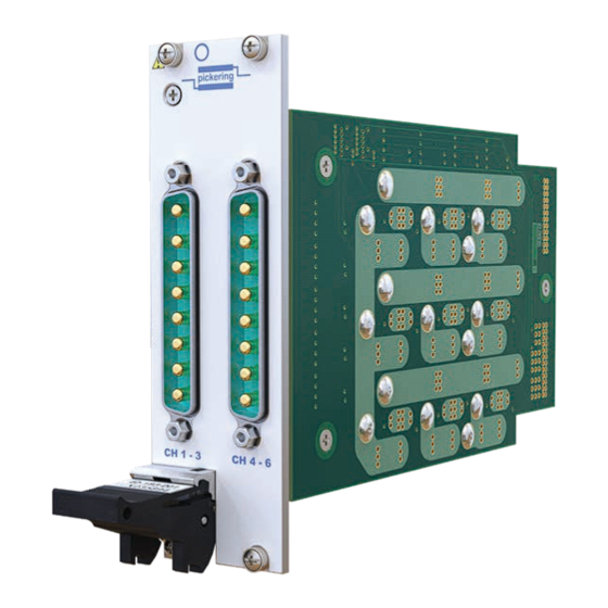
- Page 1 40-183B User Manual PXI 30 A Solid State SPST Switch Module pickeringtest.com Issue 2.1 August 2023...
- Page 2 © COPYRIGHT (2023) PICKERING INTERFACES. ALL RIGHTS RESERVED. No part of this publication may be reproduced, transmitted, transcribed, translated or stored in any form, or by any means without the written permission of Pickering Interfaces. Technical details contained within this publication are subject to change without notice.
- Page 3 Pickering Interfaces strives to fulfil all relevant environmental laws and regulations and reduce wastes and releases to the environment. Pickering Interfaces aims to design and operate products in a way that protects the environment and the health and safety of its employees, customers and the public. Pickering Interfaces endeavours to develop and manufacture products that can be produced, distributed, used and recycled, or disposed of, in a safe and environmentally friendly manner.
-
Page 4: Product Safety
If this product is heavy reference should be made to the safety instructions for provisions of lifting and moving. STATIC SENSITIVE To indicate that static sensitive devices are present and handling precautions should be followed. REED RELAY MODULE 40-110/115/120/125 30A SOLID STATE SPST SWITCH MODULE 40-183B Page (IV) Page (IV) -
Page 5: Table Of Contents
Programming The Module ............4.3 Section 5 Connector Information ..............5.1 Section 6 Trouble Shooting .................6.1 Section 7 Maintenance Information ............7.1 Switching System Test Tools ..........7.1 Relay Lookup Tables .............7.1 Appendix A Interlock Connector Wiring ............A.1 30A SOLID STATE SPST SWITCH MODULE 40-183B Page (V) - Page 6 THIS PAGE INTENTIONALLY BLANK 30A SOLID STATE SPST SWITCH MODULE 40-183B Page (VI)
-
Page 7: Warnings And Cautions
Not to be used in safety critical circuits, refer to the Pickering Interfaces’ terms & conditions of sale. This module must not be used for the switching of Mains Circuits. For the switching of voltages up to the module’s full specification, Secondary Circuit power supplies and the Device Under Test must... - Page 8 • For suitably equipped products in the event of an emergency press the red “emergency stop” button situated on the front of the unit. 30A SOLID STATE SPST SWITCH MODULE 40-183B Page (VIII) 2 AMP 1-POLE UHD MATRIX MODULES 40-575 / 576 / 577 / 578 / 579...
-
Page 9: Technical Specification
Supported by PXI or LXI Chassis y Supported by eBIRST ™ y 3 Year Warranty The 40-183B has 6 off high current SPST switches in two PXI Supported by eBIRST slots. Each SPST switch uses a fully isolated solid state relay... - Page 10 60 operations/sec Hardware Interlock Expected Life (operations): Indefinite when used within The 40-183B modules are available with an optional hardware ratings interlock. The interlock, when activated, will return all relays * For full voltage rating, signal sources to be switched must to their default unpowered state (assuming the relays are be fully isolated from mains supply and safety earth.
- Page 11 For a complete list of connection accessories and Please contact your local sales office to discuss. documentation for the 40-183B module, please refer to our 8-pin Power D-type datasheet (90-012D). PXI & CompactPCI Compliance The module is compliant with the PXI Specification 2.2.
- Page 12 SECTION 1 - TECHNICAL SPECIFICATION pickering THIS PAGE INTENTIONALLY BLANK 30A SOLID STATE SPST SWITCH MODULE 40-183B Page 1.4...
-
Page 13: Functional Description
U5-6 Daughter Board 2 +3.3V Channels 4-6 Solid State Relays Relay RL1-2, Drivers RL7-8, U19-20 RL13-14 Figure 2.1 - 30A Solid State SPST Switch 40-183B-011: Functional Block Diagram 6x SPST Switches 30A SOLID STATE SPST SWITCH MODULE 40-183B Page 2.1... -
Page 14: Hardware Interlock
HARDWARE INTERLOCK The 40-183B-011-HI modules have an interlock feature that can be used to return the relays (assuming they are fully functional) to their default unpowered state if the interlock connector is not in place or if the connection between the two interlock pins is open-circuit. - Page 15 Hardware Interlock Interlock Interlock Status Status Status PXI Gnd PXI Gnd PXI Gnd To Other Modules With Hardware Interlock Figure 2.2 - All 40-183B-011-HI Modules Enabled by a Common Signal Master +3.3V +3.3V +3.3V Module Module Module With With With...
- Page 16 SECTION 2 - TECHNICAL DESCRIPTION pickering THIS PAGE INTENTIONALLY BLANK 30A SOLID STATE SPST SWITCH MODULE 40-183B Page 2.4...
-
Page 17: Installation
Modular products require installation in a suitable PXI/LXI chassis. The module is designed for indoor use only. PREOPERATION CHECKS (UNPACKING) 1. Check the module for transport damage and report any damage immediately to Pickering Interfaces. Do not attempt to install the product if any damage is evident. -
Page 18: Hardware Installation
For a system comprising more than one chassis, turn ON the last chassis in the system followed by the penultimate, etc, and finally turn ON the external controller or chassis containing the system controller. 9. For Pickering Interfaces modular LXI installation there is no requirement to use any particular power up sequence. -
Page 19: Testing Operation
Figure 3.2 - General Soft Front Panel Icon A selector panel will appear, listing all installed Pickering PCI, PXI or LXI switch cards and resistor cards. Click on the card you wish to control, and a graphical control panel is presented allowing operation of the card. - Page 20 SECTION 3 - INSTALLATION pickering THIS PAGE INTENTIONALLY BLANK 30A SOLID STATE SPST SWITCH MODULE 40-183B Page 3.4...
-
Page 21: Programming Guide
SECTION 4 - PROGRAMMING GUIDE PROGRAMMING OPTIONS FOR PICKERING INTERFACES PXI MODULES For information on the installation and use of drivers and the programming of Pickering’s products in various software environments, please refer to the Software User Manual. This is available as a download from: https://www.pickeringtest.com/support/software-drivers-and-downloads... -
Page 22: Module Architecture
MODULE ARCHITECTURE The 40-183B-011 module is an array of 6 uncommitted SPST relays. In their default state, all signal paths are open circuit. Energising a particular relay creates a signal path between the C and A terminals. The relay module’s... -
Page 23: Programming The Module
SECTION 4 - PROGRAMMING GUIDE pickering PROGRAMMING THE MODULE Here are examples of using the drivers with the 40-183B Using PILPXI To operate a relay the user could use the simple OpBit command or the WriteSub commands OpBit DWORD sub_unit = 1;... - Page 24 SECTION 4 - PROGRAMMING GUIDE pickering Using The Interlock Function The following functions are applicable to 40-183B-011-HI modules fitted with the optional hardware interlock. Get the status of Interlock Use the attribute “ATTR_INTERLOCK_STATUS”, to the get the status of the interlock.
- Page 25 SECTION 5 - CONNECTOR INFORMATION pickering SECTION 5 - CONNECTOR INFORMATION pickering CH1-3 CH4-6 Figure 5.1 - 6 x Solid State SPST Switch 40-183B-011: Pinouts Viewed From Front Panel, Connectors are 8-pin Power D-type Plugs. 30A SOLID STATE SPST SWITCH MODULE 40-183B Page 5.1...
- Page 26 Figure 5.2 - Pinout: Hardware Interlock Connector Applicable to 40-183B-011-HI Modules With Hardware Interlock Option (4-pin 00 Series Female Connector Viewed From Front of Module) Refer to Appendix A for Wiring and Assembly Instructions Note 1: the maximum conductor size for the interlock connector is 30AWG...
-
Page 27: Trouble Shooting
PCI configuration, highlighting any potential configuration problems. Specific details of all installed Pickering switch cards are included. All the installed Pickering switch cards should be listed in the “Pilpxi information” section - if one or more cards is missing it may be possible to determine the reason by referring to the PCI configuration dump contained in the report, but interpretation of this information is far from straightforward, and the best course is to contact Pickering support: support@pickeringtest.com, if possible... - Page 28 SECTION 6 - TROUBLE SHOOTING pickering THIS PAGE INTENTIONALLY BLANK 30A SOLID STATE SPST SWITCH MODULE 40-183B Page 6.2...
-
Page 29: Maintenance Information
For PXI modules which are supported in one of Pickering Interfaces’ Modular LXI Chassis (such as the 60-102B and 60-103B) no module software update is required. If the module was introduced after the LXI chassis was manufactured the module may not be recognized, in this case the chassis firmware may need upgrading. - Page 30 A2 to C2 Inner U7 & U8 A3 to C3 U1 & U2 40-183B-011 A4 to C4 U13 & U14 A5 to C5 Outer U7 & U8 A6 to C6 U1 & U2 30A SOLID STATE SPST SWITCH MODULE 40-183B Page 7.2...
- Page 31 SECTION 7 - MAINTENANCE INFORMATION pickering Figure 7.1 - 40-183B Component Layout - Daughter Board 30A SOLID STATE SPST SWITCH MODULE 40-183B Page 7.3...
- Page 32 SECTION 7 - MAINTENANCE INFORMATION pickering THIS PAGE INTENTIONALLY BLANK 30A SOLID STATE SPST SWITCH MODULE 40-183B Page 7.4...
-
Page 33: Interlock Connector Wiring
1. Position back nut and collet on cable. 2. Strip outer jacket, braided screen and individual conductors. 4.0 mm Refer to the guideline stripping 0.5 mm dimensions shown. 2.5 mm 7.0 mm 3. Solder terminate each individual conductor. 30A SOLID STATE SPST SWITCH MODULE 40-183B Page A.1... - Page 34 Note alignment of orientation lug with colored dot on the housing. Thread 7. Apply suitable thread lock and secure the back nut to the recommended torque of 0.25 Nm. 30A SOLID STATE SPST SWITCH MODULE 40-183B Page A.2...
Need help?
Do you have a question about the 40-183B and is the answer not in the manual?
Questions and answers