
Related Manuals for Pickering 40-199


Summary of Contents for Pickering 40-199
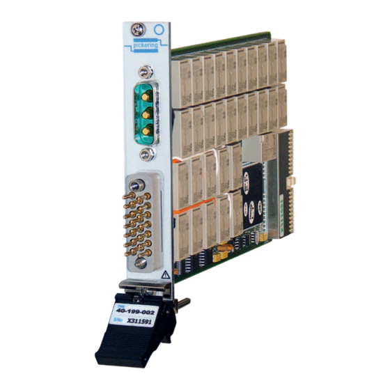
- Page 1 40-199 User Manual PXI 10 Amp Fault Insertion Switch pickeringtest.com Issue 2.5 December 2019...
- Page 2 © COPYRIGHT (2019) PICKERING INTERFACES. ALL RIGHTS RESERVED. No part of this publication may be reproduced, transmitted, transcribed, translated or stored in any form, or by any means without the written permission of Pickering Interfaces. Technical details contained within this publication are subject to change without notice.
- Page 3 Pickering Interfaces strives to fulfil all relevant environmental laws and regulations and reduce wastes and releases to the environment. Pickering Interfaces aims to design and operate products in a way that protects the environment and the health and safety of its employees, customers and the public. Pickering Interfaces endeavours to develop and manufacture products that can be produced, distributed, used and recycled, or disposed of, in a safe and environmentally friendly manner.
-
Page 4: Product Safety
If this product is heavy reference should be made to the safety instructions for provisions of lifting and moving. STATIC SENSITIVE To indicate that static sensitive devices are present and handling precautions should be followed. REED RELAY MODULE 40-110/115/120/125 10A FAULT INSERTION SWITCH 40-199 Page (IV) Page (IV) -
Page 5: Table Of Contents
Pre Operation Checks ............3.1 Hardware Installation ............3.2 Software Installation .............3.2 Testing Operation ..............3.3 Section 4 Programming Guide ..............4.1 Programming Options For Pickering PXI Cards....4.1 Module Architecture ..............4.2 Programming The Module ............4.6 Section 5 Connector Information ..............5.1 Pinout - Single Bus Version ..........5.1 Pinout - Dual Bus Version .............5.2... - Page 6 THIS PAGE INTENTIONALLY BLANK 10A FAULT INSERTION SWITCH 40-199 Page (VI)
-
Page 7: Warnings And Cautions
Not to be used in safety critical circuits, refer to the Pickering Interfaces’ terms & conditions of sale. This module must not be used for the switching of Mains Circuits. For the switching of voltages up to the module’s full specification, Secondary Circuit power supplies and the Device Under Test must... - Page 8 • For suitably equipped products in the event of an emergency press the red “emergency stop” button situated on the front of the unit. 10A FAULT INSERTION SWITCH 40-199 Page (VIII) 2 AMP 1-POLE UHD MATRIX MODULES 40-575 / 576 / 577 / 578 / 579...
- Page 9 • VISA, IVI & Kernel Drivers Supplied for Windows • Supported by PXI or LXI Chassis • 3 Year Warranty The 40-199 is a 10 Channel Fault Insertion switch designed for the simulation of fault conditions in automotive/avionics applications, involving the reliability testing of safety critical controllers.
- Page 10 SECTION 1 - TECHNICAL SPECIFICATION pickering Specifications 10A Fault Insertion Switch – 40-199 Relay Type The 40-199 is fitted with high quality electro-mechanical power relays with gold-flash over silver alloy contacts. AC Resistive Switching Specification Contact Type: Gold flash over silver alloy...
- Page 11 Kits of replacement relays are available for the majority of Pickering’s PXI switching products, simplifying servicing and Product Customization reducing down-time. Pickering PXI modules are designed and manufactured on our own Product Relay Kit flexible manufacturing lines, giving complete product control and...
- Page 12 We provide a full range of supporting cable and connector solutions for all our switching products—20 connector families with 1200+ products. We offer everything from simple mating connectors to complex cables assemblies and terminal blocks. All assemblies are manufactured by Pickering and are guaranteed to mechanically and electrically mate to our modules. Connectors & Backshells...
- Page 13 10A Fault Insertion Switch – 40-199 Programming Pickering provide kernel, IVI and VISA (NI & Keysight) drivers which are compatible with all Microsoft supported versions of Windows and popular older versions. For a list of all supporting operating systems, please see: pickeringtest.com/os...
- Page 14 SECTION 1 - TECHNICAL SPECIFICATION pickering THIS PAGE INTENTIONALLY BLANK 10A FAULT INSERTION SWITCH 40-199 Page 1.6...
-
Page 15: Functional Description
U8 & U9 U5, U6, U19, U20 TERMINATING RESISTORS R1 TO R13 BRIDGE 20-PIN GMCT +12V CONNECTOR +3.3V MODULE CONFIGURATION PCI BRIDGE CONFIGURATION Figure 2.1 - 10A Fault Insertion Switch 40-199: Functional Block Diagram 10A FAULT INSERTION SWITCH 40-199 Page 2.1... -
Page 16: Maximum Frequency Of Operations At Full Load
0.3Hz to avoid the resulting heat damaging the relay plastic components. Repeated operation at closer time intervals under full load will result in premature relay failure. 10A FAULT INSERTION SWITCH 40-199 Page 2.2... -
Page 17: Installation
Modular products require installation in a suitable PXI/LXI chassis. The module is designed for indoor use only. PREOPERATION CHECKS (UNPACKING) 1. Check the module for transport damage and report any damage immediately to Pickering Interfaces. Do not attempt to install the product if any damage is evident. -
Page 18: Hardware Installation
For a system comprising more than one chassis, turn ON the last chassis in the system followed by the penultimate, etc, and finally turn ON the external controller or chassis containing the system controller. 9. For Pickering Interfaces modular LXI installation there is no requirement to use any particular power up sequence. -
Page 19: Testing Operation
Figure 3.2 - General Soft Front Panel Icon A selector panel will appear, listing all installed Pickering PCI, PXI or LXI switch cards and resistor cards. Click on the card you wish to control, and a graphical control panel is presented allowing operation of the card. - Page 20 SECTION 3 - INSTALLATION pickering THIS PAGE INTENTIONALLY BLANK 10A FAULT INSERTION SWITCH 40-199 Page 3.4...
-
Page 21: Programming Guide
SECTION 4 - PROGRAMMING GUIDE PROGRAMMING OPTIONS FOR PICKERING INTERFACES PXI CARDS For information on the installation and use of drivers and the programming of Pickering’s products in various software environments, please refer to the Software User Manual. This is available as a download from: https://www.pickeringtest.com/support/software-drivers-and-downloads... -
Page 22: Module Architecture
SECTION 4 - PROGRAMMING GUIDE pickering MODULE ARCHITECTURE The Pickering 40-199 Fault Insertion Switch is available with 10 channels and with one or two fault buses. Single Bus 10-Chan 10A Fault Insertion Switch (40-199-001) Fault Bus Figure 4.1 - Fault Insertion Switch with 10 channels and one fault bus (40-199-001). - Page 23 SECTION 4 - PROGRAMMING GUIDE pickering Mode B comprises sub-units with separate switch functions. In the 40-199-001, Sub-units 2 and 3 partition the card according to the switch functionality. SUB-UNIT 2: consists of Break Relays for each channel. SUB-UNIT 3: consists of Fault insertion Bus 1 for each channel.
- Page 24 Figure 4.3 - Fault Insertion Switch with 10 channels and two fault buses (40-199-002). The Pickering 40-199-002 module is designed with 4 sub-units. There are 2 modes of operation embedded within the card. Mode A allows user to control all switches within one sub-unit and Mode B partitions the switches into different sub-units with respect to their function.
- Page 25 SECTION 4 - PROGRAMMING GUIDE pickering Mode B comprises sub-units with separate switch functions. In the 40-199-002, Sub-units 2, 3 and 4 partition the card according to the switch functionality. SUB-UNIT 2: consists of Break Relays for each channel. SUB-UNIT 3: consists of Fault insertion Bus 1 for each channel.
-
Page 26: Programming The Module
SECTION 4 - PROGRAMMING GUIDE pickering PROGRAMMING THE MODULE Here are examples of using the drivers with the 40-199-002 (10-channel, dual bus version) Using PILPXI To operate a relay the user could use the simple OpBit command or the WriteSub commands OpBit DWORD sub_unit = 1;... - Page 27 // Operates the channel 1 break relay pi40iv_Disconnect(vi, comA1, chA1); // Releases the channel 1 break relay pi40iv_Connect(vi, comA6, chA6); // Operates the channel 3, fault 1 relay The IVI Swtch driver specification contains no bulk setting capabilities. 10A FAULT INSERTION SWITCH 40-199 Page 4.7...
- Page 28 SECTION 4 - PROGRAMMING GUIDE pickering Table 4.1 - Channel Name Table for 40-199-001 (10-channel, single bus) BIT / RELAY FUNCTION / CHANNEL NAME CROSS REFERENCE TABLE (40-199-001) Sub- IVI Channel Sub- IVI Channel Function Function Unit Name Unit Name...
- Page 29 SECTION 4 - PROGRAMMING GUIDE pickering Table 4.2 - Channel Name Table for 40-199-002 (10-channel, dual bus) BIT / RELAY FUNCTION / CHANNEL NAME CROSS REFERENCE TABLE (40-198-002) Sub- IVI Channel Sub- IVI Channel Function Function Unit Name Unit Name...
- Page 30 SECTION 4 - PROGRAMMING GUIDE pickering THIS PAGE INTENTIONALLY BLANK 10A FAULT INSERTION SWITCH 40-199 Page 4.10...
-
Page 31: Pinout - Single Bus Version
Refer to the Warnings and Cautions at the front of this manual. PINOUT - SINGLE BUS VERSION pickering No Connection Fault Bus Figure 5.1 - Pinouts: 10A Fault Insertion Module 40-199-001 (10-channel, single bus) (3-pin Male Power D-type Connector & 20-pin Male GMCT Connector) 10A FAULT INSERTION SWITCH 40-199 Page 5.1... -
Page 32: Pinout - Dual Bus Version
PINOUT - DUAL BUS VERSION pickering Fault Bus 1 Fault Bus 2 Figure 5.2 - Pinouts: 10A Fault Insertion Module 40-199-002 (10-channel, dual bus) (3-pin Male Power D-type Connector & 20-pin Male GMCT Connector) 10A FAULT INSERTION SWITCH 40-199 Page 5.2... -
Page 33: Trouble Shooting
PCI configuration, highlighting any potential configuration problems. Specific details of all installed Pickering switch cards are included. All the installed Pickering switch cards should be listed in the “Pilpxi information” section - if one or more cards is missing it may be possible to determine the reason by referring to the PCI configuration dump contained in the report, but interpretation of this information is far from straightforward, and the best course is to contact Pickering support: support@pickeringtest.com, if possible... - Page 34 SECTION 6 - TROUBLE SHOOTING pickering THIS PAGE INTENTIONALLY BLANK 10A FAULT INSERTION SWITCH 40-199 Page 6.2...
-
Page 35: Maintenance Information
For PXI modules which are supported in one of Pickering Interfaces’ Modular LXI Chassis (such as the 60-102B and 60-103B) no module software update is required. If the module was introduced after the LXI chassis was manufactured the module may not be recognized, in this case the chassis firmware may need upgrading. - Page 36 The table shows which relays are fitted to each version of the module; Relays highlighted in blue are fitted to both the -001 and -002. versions, those highlighted in yellow are only fitted to the -002. Table 7.1 - Fault Insertion Switch 40-199-001/002 - Relay Look-Up Table RELAY LOOK-UP TABLE - 40-199-001/002...
- Page 37 RL21 RL11 RL22 RL12 RL23 RL13 RL24 RL14 RL25 RL15 RL10 RL26 RL16 RL27 RL17 RL28 RL18 SPARE RL29 RL19 RL30 RL20 Figure 7.1 - 10A Fault Insertion Switch 40-199-001/002: Component Layout 10A FAULT INSERTION SWITCH 40-199 Page 7.3...
- Page 38 SECTION 7 - MAINTENANCE INFORMATION pickering THIS PAGE INTENTIONALLY BLANK 10A FAULT INSERTION SWITCH 40-199 Page 7.4...
Need help?
Do you have a question about the 40-199 and is the answer not in the manual?
Questions and answers