
Related Manuals for Pickering PXI 40-197


Summary of Contents for Pickering PXI 40-197
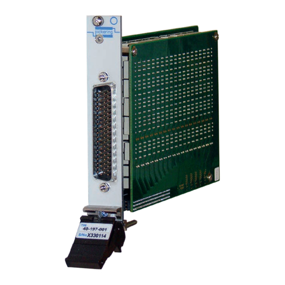
- Page 1 40-197 User Manual PXI 2 Amp Fault Insertion Switch pickeringtest.com Issue 2.5 December 2019...
- Page 2 © COPYRIGHT (2019) PICKERING INTERFACES. ALL RIGHTS RESERVED. No part of this publication may be reproduced, transmitted, transcribed, translated or stored in any form, or by any means without the written permission of Pickering Interfaces. Technical details contained within this publication are subject to change without notice.
- Page 3 Pickering Interfaces strives to fulfil all relevant environmental laws and regulations and reduce wastes and releases to the environment. Pickering Interfaces aims to design and operate products in a way that protects the environment and the health and safety of its employees, customers and the public. Pickering Interfaces endeavours to develop and manufacture products that can be produced, distributed, used and recycled, or disposed of, in a safe and environmentally friendly manner.
-
Page 4: Product Safety
PRODUCT SAFETY SAFETY SYMBOLS The following safety symbols may be used on the product and throughout the product documentation. MEANING / DESCRIPTION SYMBOL PROTECTIVE EARTH (GROUND) To identify any terminal which is intended for connection to an external conductor for protection against electric shock in case of a fault, or the terminal of a protective earth (ground) electrode. -
Page 5: Table Of Contents
Pre Operation Checks ............3.1 Hardware Installation ............3.2 Software Installation .............3.2 Testing Operation ..............3.3 Section 4 Programming Guide ..............4.1 Programming Options For Pickering PXI Modules ....4.1 Module Architecture ..............4.2 Programming The Module ............4.4 Using Pickering Drivers in LabVIEW ........4.15 Section 5 Connector Information ..............5.1 Section 6 Trouble Shooting .................6.1... - Page 6 THIS PAGE INTENTIONALLY BLANK 2A FAULT INSERTION SWITCH 40-197 Page (VI)
-
Page 7: Warnings And Cautions
Not to be used in safety critical circuits, refer to the Pickering Interfaces’ terms & conditions of sale. This module must not be used for the switching of Mains Circuits. For the switching of voltages up to the module’s full specification, Secondary Circuit power supplies and the Device Under Test must... - Page 8 CAUTION - PRODUCT DOCUMENTATION SYMBOL Suitably qualified & trained users should ensure that the accompanying documentation is fully read and understood before attempting to install or operate the product. SAFETY INSTRUCTIONS SAFETY INSTRUCTIONS All cleaning and servicing requires the equipment to be isolated and disconnected from the power source and user I/O signals (refer to the Maintenance Section).
- Page 9 • Suitable for Automotive ECU Burn-in/Endurance Test Applications • High Density Low Cost Solution, Bridging the Gap Between Pickering’s Simpler Fault Insertion Modules & More Complex FIBO BRIC Solutions • Simulation of Various Types of Electrical Fault, Enabling Rigorous Fault Testing •...
- Page 10 SECTION 1 - TECHNICAL SPECIFICATION Specifications pickering 2A Fault Insertion Switch – 40-197 Relay Type Mechanical Characteristics The 40-197 is fitted with high quality electro-mechanical relays with Single slot 3U PXI (CompactPCI card). palladium-ruthenium gold covered contacts. A spare relay is built...
- Page 11 Kits of replacement relays are available for the majority of Pickering’s PXI switching products, simplifying servicing and Product Customization reducing down-time. Pickering PXI modules are designed and manufactured on our own Product Relay Kit flexible manufacturing lines, giving complete product control and...
- Page 12 We provide a full range of supporting cable and connector solutions for all our switching products—20 connector families with 1200+ products. We offer everything from simple mating connectors to complex cables assemblies and terminal blocks. All assemblies are manufactured by Pickering and are guaranteed to mechanically and electrically mate to our modules. Connectors & Backshells...
- Page 13 2A Fault Insertion Switch – 40-197A Programming Pickering provide kernel, IVI and VISA (NI & Keysight) drivers which are compatible with all Microsoft supported versions of Windows and popular older versions. For a list of all supporting operating systems, please see: pickeringtest.com/os...
- Page 14 SECTION 1 - TECHNICAL SPECIFICATION pickering THIS PAGE INTENTIONALLY BLANK 2A FAULT INSERTION SWITCH 40-197 Page 1.6...
-
Page 15: Technical Description
SECTION 2 - TECHNICAL DESCRIPTION pickering SECTION 2 - TECHNICAL DESCRIPTION FUNCTIONAL DESCRIPTION A functional block diagram is provided in Figure 2.1. The Fault Insertion Switch is powered by a +5V input via Compact PCI connector J1. The interface to the user test equipment is via the front panel mounted 78-pin male D-type connector, J2. - Page 16 SECTION 2 - TECHNICAL DESCRIPTION pickering THIS PAGE INTENTIONALLY BLANK 2A FAULT INSERTION SWITCH 40-197 Page 2.2...
-
Page 17: Installation
Modular products require installation in a suitable PXI/LXI chassis. The module is designed for indoor use only. PREOPERATION CHECKS (UNPACKING) 1. Check the module for transport damage and report any damage immediately to Pickering Interfaces. Do not attempt to install the product if any damage is evident. -
Page 18: Hardware Installation
For a system comprising more than one chassis, turn ON the last chassis in the system followed by the penultimate, etc, and finally turn ON the external controller or chassis containing the system controller. 9. For Pickering Interfaces modular LXI installation there is no requirement to use any particular power up sequence. -
Page 19: Testing Operation
Figure 3.2 - General Soft Front Panel Icon A selector panel will appear, listing all installed Pickering PCI, PXI or LXI switch cards and resistor cards. Click on the card you wish to control, and a graphical control panel is presented allowing operation of the card. - Page 20 SECTION 3 - INSTALLATION pickering THIS PAGE INTENTIONALLY BLANK 2A FAULT INSERTION SWITCH 40-197 Page 3.4...
-
Page 21: Programming Guide
SECTION 4 - PROGRAMMING GUIDE PROGRAMMING OPTIONS FOR PICKERING INTERFACES PXI MODULES For information on the installation and use of drivers and the programming of Pickering’s products in various software environments, please refer to the Software User Manual. This is available as a download from: https://www.pickeringtest.com/support/software-drivers-and-downloads... -
Page 22: Module Architecture
MODULE ARCHITECTURE The Pickering 40-197 Fault Insertion Switch is available in versions with either 34 or 16 channels, both versions have four fault buses which can be switched to one of two fault connections as shown in the diagrams below: Figure 4.1 - Fault Insertion Switch with 34 channels and four fault buses (40-197-001) - Page 23 SECTION 4 - PROGRAMMING GUIDE pickering The Pickering 40-197 module is designed with 7 sub-units. There are 2 modes of operation embedded within the card. Mode A allows user to control all switches within one sub-unit and Mode B partitions the switches into different sub-units with respect to their function.
-
Page 24: Programming The Module
SECTION 4 - PROGRAMMING GUIDE pickering PROGRAMMING THE MODULE Here are examples of using the drivers with the 40-197-001 (34-channel version) Using PILPXI To operate a relay the user could use the simple OpBit command or the WriteSub commands OpBit (Single Sub-Unit) DWORD sub_unit = 1;... - Page 25 SECTION 4 - PROGRAMMING GUIDE pickering sub-unit = 3 // Fault bus 1 data[0] = 1; // Fault bus 1 Channel 1 selected data[1] = 0; PIL_WriteSub( card_num, sub_unit, data); sub-unit = 4 // Fault bus 2 data[0] = 0;...
- Page 26 SECTION 4 - PROGRAMMING GUIDE pickering setChannelPattern (Multiple Sub-Units) // Sub-units 2, 3, 4, 5 and 6 are 34 bits wide. Each of these sub-units require 2 // ViUInt32 to hold the entire pattern. Subunit 7 is 4 bits wide and requires 1 ViUInt32...
- Page 27 SECTION 4 - PROGRAMMING GUIDE pickering Using pi40iv The IVI driver has no special labelling for this card and treats the array of switches as a simple array, labelling the channels using the normal com./ch labelling tags. pi40iv (Single Sub-Unit) pi40iv_Connect(vi, comA1, chA1);...
- Page 28 SECTION 4 - PROGRAMMING GUIDE pickering Table 4.1 - Channel Name Table for 40-197-001 (34-channel, quad bus) BIT / RELAY FUNCTION / CHANNEL NAME CROSS REFERENCE TABLE (40-197-001) Sub- Sub- Function IVI Channel Name Function IVI Channel Name Unit Unit...
- Page 29 SECTION 4 - PROGRAMMING GUIDE pickering Table 4.1 - Channel Name Table for 40-197-001 (34-channel, quad bus) - Continued BIT / RELAY FUNCTION / CHANNEL NAME CROSS REFERENCE TABLE (40-197-001) Sub- Sub- Function IVI Channel Name Function IVI Channel Name...
- Page 30 SECTION 4 - PROGRAMMING GUIDE pickering Table 4.1 - Channel Name Table for 40-197-001 (34-channel, quad bus) - Continued BIT / RELAY FUNCTION / CHANNEL NAME CROSS REFERENCE TABLE (40-197-001) Sub- Sub- Function IVI Channel Name Function IVI Channel Name...
- Page 31 SECTION 4 - PROGRAMMING GUIDE pickering Table 4.1 - Channel Name Table for 40-197-001 (34-channel, quad bus) - Continued BIT / RELAY FUNCTION / CHANNEL NAME CROSS REFERENCE TABLE (40-197-001) Sub- Sub- Function IVI Channel Name Function IVI Channel Name...
- Page 32 SECTION 4 - PROGRAMMING GUIDE pickering Table 4.1 - Channel Name Table for 40-197-001 (34-channel, quad bus) - Continued BIT / RELAY FUNCTION / CHANNEL NAME CROSS REFERENCE TABLE (40-197-001) Sub- Sub- Function IVI Channel Name Function IVI Channel Name...
- Page 33 SECTION 4 - PROGRAMMING GUIDE pickering Table 4.2 - Channel Name Table for 40-197-002 (16-channel, quad bus) BIT / RELAY FUNCTION / CHANNEL NAME CROSS REFERENCE TABLE (40-197-002) Sub- Sub- Function IVI Channel Name Function IVI Channel Name Unit Unit...
- Page 34 SECTION 4 - PROGRAMMING GUIDE pickering Table 4.2 - Channel Name Table for 40-197-002 (16-channel, quad bus) - Continued BIT / RELAY FUNCTION / CHANNEL NAME CROSS REFERENCE TABLE (40-197-002) Sub- Sub- Function IVI Channel Name Function IVI Channel Name...
-
Page 35: Using Pickering Drivers In Labview
USING PICKERING DRIVERS IN LabVIEW Most Pickering drivers include a LabVIEW wrapper to permit full operation of the Pickering product from the LabVIEW environment. These wrappers are normally installed to the current LabVIEW folder system during installation of the Pickering driver. - Page 36 SECTION 4 - PROGRAMMING GUIDE pickering THIS PAGE INTENTIONALLY BLANK 2A FAULT INSERTION SWITCH 40-197 Page 4.16...
-
Page 37: Connector Information
SECTION 5 - CONNECTOR INFORMATION pickering SECTION 5 - CONNECTOR INFORMATION FP_GND FP_GND Figure 5.1 - Pinouts: 2A Fault Insertion Module 40-197-001 - 34-Channel, Quad Bus (78-pin Male D-Type Connector Viewed from Front of Module) 2A FAULT INSERTION SWITCH 40-197... - Page 38 SECTION 5 - CONNECTOR INFORMATION pickering FP_GND FP_GND Figure 5.2 - Pin Outs: 2A Fault Insertion Module 40-197-002 - 16-Channel, Quad Bus (78-pin Male D-Type Connector Viewed from Front of Module) 2A FAULT INSERTION SWITCH 40-197 Page 5.2...
-
Page 39: Trouble Shooting
PCI configuration, highlighting any potential configuration problems. Specific details of all installed Pickering switch cards are included. All the installed Pickering switch cards should be listed in the “Pilpxi information” section - if one or more cards is missing it may be possible to determine the reason by referring to the PCI configuration dump contained in the report, but interpretation of this information is far from straightforward, and the best course is to contact Pickering support: support@pickeringtest.com, if possible... - Page 40 SECTION 6 - TROUBLE SHOOTING pickering THIS PAGE INTENTIONALLY BLANK 2A FAULT INSERTION SWITCH 40-197 Page 6.2...
-
Page 41: Maintenance Information
For PXI modules which are supported in one of Pickering Interfaces’ Modular LXI Chassis (such as the 60-102B and 60-103B) no module software update is required. If the module was introduced after the LXI chassis was manufactured the module may not be recognized, in this case the chassis firmware may need upgrading. - Page 42 SECTION 7 - MAINTENANCE INFORMATION pickering RELAY LOOK-UP TABLES The table shows which relays are fitted to each version of the module; Relays highlighted in blue are fitted to both the -001 and -002. versions, those highlighted in yellow are only fitted to the -001.
- Page 43 SECTION 7 - MAINTENANCE INFORMATION pickering RL10 RL11 RL12 RL13 RL14 RL15 RL16 RL17 RL18 RL19 RL20 RL21 RL22 RL23 RL24 RL25 RL26 RL27 RL28 RL29 RL30 RL31 RL32 RL33 RL34 RL35 RL36 RL37 RL38 RL39 RL40 RL41 RL42 RL43...
- Page 44 SECTION 7 - MAINTENANCE INFORMATION pickering THIS PAGE INTENTIONALLY BLANK 2A FAULT INSERTION SWITCH 40-197 Page 7.4...
Need help?
Do you have a question about the PXI 40-197 and is the answer not in the manual?
Questions and answers