
Related Manuals for Pickering 40-190B


Summary of Contents for Pickering 40-190B
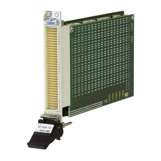
- Page 1 40-190B User Manual PXI 2 Amp Fault Insertion Switch pickeringtest.com Issue 6.4 July 2023...
- Page 2 © COPYRIGHT (2023) PICKERING INTERFACES. ALL RIGHTS RESERVED. No part of this publication may be reproduced, transmitted, transcribed, translated or stored in any form, or by any means without the written permission of Pickering Interfaces. Technical details contained within this publication are subject to change without notice.
- Page 3 Pickering Interfaces strives to fulfil all relevant environmental laws and regulations and reduce wastes and releases to the environment. Pickering Interfaces aims to design and operate products in a way that protects the environment and the health and safety of its employees, customers and the public. Pickering Interfaces endeavours to develop and manufacture products that can be produced, distributed, used and recycled, or disposed of, in a safe and environmentally friendly manner.
-
Page 4: Product Safety
If this product is heavy reference should be made to the safety instructions for provisions of lifting and moving. STATIC SENSITIVE To indicate that static sensitive devices are present and handling precautions should be followed. REED RELAY MODULE 40-110/115/120/125 2A FAULT INSERTION SWITCH 40-190B Page (IV) Page (IV) -
Page 5: Table Of Contents
Hardware Installation ............3.2 Software Installation .............3.2 Testing Operation ..............3.3 Section 4 Programming Guide ..............4.1 Programming Options For Pickering PXI Modules ....4.1 Module Architecture ..............4.2 Programming The Module ............4.6 Using Pickering Drivers in LabVIEW ........4.12 Relay/Bit Look-Up Tables - Single Sub-Units .....4.13 Relay/Bit Look-Up Tables - Multiple Sub-Units ....4.21... - Page 6 THIS PAGE INTENTIONALLY BLANK 2A FAULT INSERTION SWITCH 40-190B Page (VI)
-
Page 7: Warnings And Cautions
Not to be used in safety critical circuits, refer to the Pickering Interfaces’ terms & conditions of sale. This module must not be used for the switching of Mains Circuits. For the switching of voltages up to the module’s full specification, Secondary Circuit power supplies and the Device Under Test must... - Page 8 • For suitably equipped products in the event of an emergency press the red “emergency stop” button situated on the front of the unit. 2A FAULT INSERTION SWITCH 40-190B Page (VIII) 2 AMP 1-POLE UHD MATRIX MODULES 40-575 / 576 / 577 / 578 / 579...
-
Page 9: Technical Specification
40-190B 74, 64 or 32 1 or 2 4 or 8 165V The 40-190B is a Fault Insertion switch available with 74, 64 or 40-191A 32 channels. It is primarily designed for the simulation of fault 40-192 200V conditions in automotive & avionics applications involving the... - Page 10 Versions With Normally Closed Through Relays Monitor1 Fault MUX Monitor2 40-190B-102 Dual Bus, 64-Channel Fault Insertion Switch Schematic (40-190B-101 Has 1 Fault Bus) Monitor1 Fault MUX Monitor2 40-190B-002 Dual Bus, 74-Channel Fault Insertion Switch Schematic (40-190B-001 Has 1 Fault Bus)
- Page 11 Versions With Normally Open Through Relays Monitor1 Fault MUX Monitor2 40-190B-402 Dual Bus, 64-Channel Fault Insertion Switch Schematic (40-190B-401 Has 1 Fault Bus) Monitor1 Fault MUX Monitor2 40-190B-302 Dual Bus, 74-Channel Fault Insertion Switch Schematic (40-190B-301 Has 1 Fault Bus)
- Page 12 Specifications 2A Fault Insertion Switch – 40-190B Switching Specification - Relay Type Versions With Normally Open Through Relays The 40-190B is fitted with high quality electro-mechanical relays Switch Type Electro-mechanical with palladium-ruthenium gold covered contacts. A spare relay Contact Type:...
- Page 13 Specifications & Ordering Information 2A Fault Insertion Switch – 40-190B Note: The 40-190B is suitable for carrying signals such as CAN to Product Order Codes 1Mbps & FlexRay to 20Mbps (10Mbps per channel path) Fault Insertion Switches With Normally Closed...
- Page 14 We provide a full range of supporting cable and connector solutions for all our switching products—20 connector families with 1200+ products. We offer everything from simple mating connectors to complex cables assemblies and terminal blocks. All assemblies are manufactured by Pickering and are guaranteed to mechanically and electrically mate to our modules. Connectors & Backshells...
- Page 15 2A Fault Insertion Switch – 40-190B Programming Pickering provide kernel, IVI and VISA (NI & Keysight) drivers which are compatible with all Microsoft supported versions of Windows and popular older versions. For a list of all supporting operating systems, please see: pickeringtest.com/os...
- Page 16 SECTION 1 - TECHNICAL SPECIFICATION pickering THIS PAGE INTENTIONALLY BLANK 2A FAULT INSERTION SWITCH 40-190B Page 1.8...
-
Page 17: Technical Description
Inter-PCB Connection Mother Board Relay Interface Drivers & Control Logic Electro-mechanical PXI 2 AMP FAULT INSERTION Relays RL1-96 & 223-232 SWITCH MODULE 40-190B Figure 2.1 - 2A Fault Insertion Switch 40-190B: Functional Block Diagram 2A FAULT INSERTION SWITCH 40-190B Page 2.1... - Page 18 SECTION 2 - TECHNICAL DESCRIPTION pickering THIS PAGE INTENTIONALLY BLANK 2A FAULT INSERTION SWITCH 40-190B Page 2.2...
-
Page 19: Installation
Modular products require installation in a suitable PXI/LXI chassis. The module is designed for indoor use only. PREOPERATION CHECKS (UNPACKING) 1. Check the module for transport damage and report any damage immediately to Pickering Interfaces. Do not attempt to install the product if any damage is evident. -
Page 20: Hardware Installation
For a system comprising more than one chassis, turn ON the last chassis in the system followed by the penultimate, etc, and finally turn ON the external controller or chassis containing the system controller. 9. For Pickering Interfaces modular LXI installation there is no requirement to use any particular power up sequence. -
Page 21: Testing Operation
Figure 3.2 - General Soft Front Panel Icon A selector panel will appear, listing all installed Pickering PCI, PXI or LXI switch cards and resistor cards. Click on the card you wish to control, and a graphical control panel is presented allowing operation of the card. - Page 22 SECTION 3 - INSTALLATION pickering THIS PAGE INTENTIONALLY BLANK 2A FAULT INSERTION SWITCH 40-190B Page 3.4...
-
Page 23: Programming Guide
SECTION 4 - PROGRAMMING GUIDE PROGRAMMING OPTIONS FOR PICKERING INTERFACES PXI MODULES For information on the installation and use of drivers and the programming of Pickering’s products in various software environments, please refer to the Software User Manual. This is available as a download from: https://www.pickeringtest.com/support/software-drivers-and-downloads... -
Page 24: Module Architecture
MODULE ARCHITECTURE The Pickering 40-190B Fault Insertion Switch is available with 74, 64 or 32 channels and with one or two fault buses. Each version is also available with normally closed or normally open through relays. The architecture is... - Page 25 Monitor1 Fault MUX Figure 4.3 - Fault Insertion Switch with one fault bus and normally open through relays. The maximum channel count “N” is 74 (40-190B-301), 64 (40-190B-401) or 32 (40-190B-501). Monitor1 Fault MUX Monitor2 Figure 4.4 - Fault Insertion Switch with two fault buses and normally open through relays.
- Page 26 Monitor 1 (m = Fault connection) (N * 3) + 10 Monitor 2 Example - the address of the Monitor 1 on a 40-190B-102 will be (64 * 3) + 9 or 201 2A FAULT INSERTION SWITCH 40-190B Page 4.4...
- Page 27 40-190B-201 Sub-Unit Allocation The 40-190B is available with single or dual fault insertion buses and is controlled with 5 sub-units or 7 sub-units respectively. There are 2 modes of operation embedded within the card. Mode A allows the user to control all switches within one sub-unit and Mode B partitions the switches into different sub-units with respect to their function.
- Page 28 SECTION 4 - PROGRAMMING GUIDE pickering SOFTWARE ARCHITECTURE - SINGLE FAULT BUS Figure 4.5 - Fault Insertion Switch 40-190B Sub-Unit Allocation - Single Fault Bus SOFTWARE ARCHITECTURE - DUAL FAULT BUS Figure 4.6 - Fault Insertion Switch 40-190B Sub-Unit Allocation - Dual Fault Bus 2A FAULT INSERTION SWITCH 40-190B Page 4.6...
-
Page 29: Programming The Module
Programming The 40-190B Single and Dual Fault Bus Versions Using a Single Sub-Unit (Mode A) Here are examples of using drivers with the 40-190B using sub-unit 1. The examples shown are for the 40-190B- 002 (74-channel, dual bus), other versions operate in the same way but with different numbers of bits in the sub-unit. - Page 30 // Operates the channel 2, Fault Bus 2 relay pi40iv_Connect(vi, comA228, chA228); // Connects input F6 to Fault Bus 2 pi40iv_Connect(vi, comA232, chA232); // Connects Monitor 2 to Fault Bus 2 The IVI Swtch driver specification contains no bulk setting capabilities. 2A FAULT INSERTION SWITCH 40-190B Page 4.8...
- Page 31 Programming The 40-190B Dual Fault Bus Versions Using Multiple Sub-Units (Mode B) Here are examples of using drivers with the dual fault bus versions of the 40-190B using sub-units 2-7. The examples shown are for the 40-190B-002 (74-channel, dual bus), other dual bus versions operate in the same way but with different numbers of bits in the sub-units.
- Page 32 // Operates the channel 2, Fault Bus 2 relay pi40iv_Connect(vi, comF, chF1); // Connects input F5 to Fault Bus 2 pi40iv_Connect(vi, comG, chG2); // Connects Monitor 2 to Fault Bus 2 The IVI Swtch driver specification contains no bulk setting capabilities. 2A FAULT INSERTION SWITCH 40-190B Page 4.10...
- Page 33 Programming The 40-190B Single Fault Bus Versions Using Multiple Sub-Units (Mode B) Here are examples of using drivers with the single fault bus versions of the 40-190B using sub-units 2-5. The examples shown are for the 40-190B-201 (32-channel, single bus), other single bus versions operate in the same way but with different numbers of bits in the sub-units.
- Page 34 // Operates the channel 2, Fault Bus 1 relay pi40iv_Connect(vi, comD, chD1); // Connects input F1 to Fault Bus 1 pi40iv_Connect(vi, comE, chE1); // Connects Monitor 1 to Fault Bus 1 The IVI Swtch driver specification contains no bulk setting capabilities. 2A FAULT INSERTION SWITCH 40-190B Page 4.12...
-
Page 35: Using Pickering Drivers In Labview
USING PICKERING DRIVERS IN LabVIEW Most Pickering drivers include a LabVIEW wrapper to permit full operation of the Pickering product from the LabVIEW environment. These wrappers are normally installed to the current LabVIEW folder system during installation of the Pickering driver. - Page 36 SECTION 4 - PROGRAMMING GUIDE pickering RELAY/BIT LOOK-UP TABLES - SINGLE SUB-UNIT CONTROL Table 4.1 - Relay/Bit Table for 40-190B-001 & 40-190B-301 (74-channel, single bus versions) for Sub-Unit 1 Including IVI Channel Names BIT TO RELAY FUNCTION CROSS REFERENCE TABLE (40-190B-001/301)
- Page 37 SECTION 4 - PROGRAMMING GUIDE pickering Table 4.2 - Relay/Bit Table for 40-190B-101 & 40-190B-401 (64-channel, single bus versions) for Sub-Unit 1 Including IVI Channel Names BIT TO RELAY FUNCTION CROSS REFERENCE TABLE (40-190B-101/401) Sub- IVI Channel Sub- IVI Channel...
- Page 38 SECTION 4 - PROGRAMMING GUIDE pickering Table 4.3 - Relay/Bit Table for 40-190B-201 & 40-190B-501 (32-channel, single bus versions) for Sub-Unit 1 Including IVI Channel Names BIT TO RELAY FUNCTION CROSS REFERENCE TABLE (40-190B-201/501) Sub- IVI Channel Sub- IVI Channel...
- Page 39 SECTION 4 - PROGRAMMING GUIDE pickering Table 4.4 - Relay/Bit Table for 40-190B-002 & 40-190B-302 (74-channel, dual bus versions) for Sub-Unit 1 Including IVI Channel Names BIT TO RELAY FUNCTION CROSS REFERENCE TABLE (40-190B-002/302) Sub- IVI Channel Sub- IVI Channel...
- Page 40 SECTION 4 - PROGRAMMING GUIDE pickering Table 4.4 Continued - Relay/Bit Table for 40-190B-002 & 40-190B-302 (74-channel, dual bus versions) for Sub-Unit 1 Including IVI Channel Names BIT TO RELAY FUNCTION CROSS REFERENCE TABLE (40-190B-002/302) Sub- IVI Channel Sub- IVI Channel...
- Page 41 SECTION 4 - PROGRAMMING GUIDE pickering Table 4.5 - Relay/Bit Table for 40-190B-102 & 40-190B-302 (64-channel, dual bus versions) for Sub-Unit 1 Including IVI Channel Names BIT TO RELAY FUNCTION CROSS REFERENCE TABLE (40-190B-102/402) Sub- IVI Channel Sub- IVI Channel...
- Page 42 SECTION 4 - PROGRAMMING GUIDE pickering Table 4.5 Continued - Relay/Bit Table for 40-190B-102 & 40-190B-402 (64-channel, dual bus versions) for Sub-Unit 1 Including IVI Channel Names BIT TO RELAY FUNCTION CROSS REFERENCE TABLE (40-190B-102/402) Sub- IVI Channel Sub- IVI Channel...
- Page 43 SECTION 4 - PROGRAMMING GUIDE pickering Table 4.6 - Relay/Bit Table for 40-190B-202 & 40-190B-502 (32-channel, dual bus versions) for Sub-Unit 1 Including IVI Channel Names BIT TO RELAY FUNCTION CROSS REFERENCE TABLE (40-190B-202/502) Sub- IVI Channel Sub- IVI Channel...
- Page 44 SECTION 4 - PROGRAMMING GUIDE pickering RELAY/BIT LOOK-UP TABLES - MULTIPLE SUB-UNIT CONTROL Table 4.7 - Relay/Bit Table for 40-190B-001 & 40-190B-301 (74-channel, single bus versions) for Sub-Units 2 to 5 Including IVI Channel Names BIT TO RELAY FUNCTION CROSS REFERENCE TABLE (40-190B-001/301)
- Page 45 SECTION 4 - PROGRAMMING GUIDE pickering Table 4.8 - Relay/Bit Table for 40-190B-101 & 40-190B-401 (64-channel, single bus versions) for Sub-Unit 2 to 5 Including IVI Channel Names BIT TO RELAY FUNCTION CROSS REFERENCE TABLE (40-190B-101/401) Sub- IVI Channel Sub-...
- Page 46 SECTION 4 - PROGRAMMING GUIDE pickering Table 4.9 - Relay/Bit Table for 40-190B-201 & 40-190B-501 (32-channel, single bus versions) for Sub-Units 2 to 5 Including IVI Channel Names BIT TO RELAY FUNCTION CROSS REFERENCE TABLE (40-190B-201/501) Sub- IVI Channel Sub-...
- Page 47 SECTION 4 - PROGRAMMING GUIDE pickering Table 4.10 - Relay/Bit Table for 40-190B-002 & 40-190B-302 (74-channel, dual bus versions) for Sub-Units 2 to 7 Including IVI Channel Names BIT TO RELAY FUNCTION CROSS REFERENCE TABLE (40-190B-002/302) Sub- IVI Channel Sub-...
- Page 48 SECTION 4 - PROGRAMMING GUIDE pickering Table 4.10 Continued - Relay/Bit Table for 40-190B-002 & 40-190B-302 (74-channel, dual bus versions) for Sub-Units 2 to 7 Including IVI Channel Names BIT TO RELAY FUNCTION CROSS REFERENCE TABLE (40-190B-002/302) Sub- IVI Channel...
- Page 49 SECTION 4 - PROGRAMMING GUIDE pickering Table 4.11 - Relay/Bit Table for 40-190B-102 & 40-190B-402 (64-channel, dual bus versions) for Sub-Units 2 to 7 Including IVI Channel Names BIT TO RELAY FUNCTION CROSS REFERENCE TABLE (40-190B-102/402) Sub- IVI Channel Sub-...
- Page 50 SECTION 4 - PROGRAMMING GUIDE pickering Table 4.11 Continued - Relay/Bit Table for 40-190B-102 & 40-190B-402 (64-channel, dual bus versions) for Sub-Units 2 to 7 Including IVI Channel Names BIT TO RELAY FUNCTION CROSS REFERENCE TABLE (40-190B-102/402) Sub- IVI Channel...
- Page 51 SECTION 4 - PROGRAMMING GUIDE pickering Table 4.12 - Relay/Bit Table for 40-190B-202 & 40-190B-502 (32-channel, dual bus versions) for Sub-Units 2 to 7 Including IVI Channel Names BIT TO RELAY FUNCTION CROSS REFERENCE TABLE (40-190B-202/502) Sub- IVI Channel Sub-...
- Page 52 SECTION 4 - PROGRAMMING GUIDE pickering THIS PAGE INTENTIONALLY BLANK 2A FAULT INSERTION SWITCH 40-190B Page 4.30...
-
Page 53: Connector Information
SECTION 5 - CONNECTOR INFORMATION MON1 Fault MUX MON1 Figure 5.1 - Pinouts: 2A Fault Insertion Module 40-190B-001 (74-channel, single bus version with normally closed through relays) 160-pin male DIN 41612 connector viewed from front of module. 2A FAULT INSERTION SWITCH 40-190B... - Page 54 Fault MUX MON2 MON1 MON2 Figure 5.2 - Pinouts: 2A Fault Insertion Module 40-190B-002 (74-channel, dual bus version with normally closed through relays) 160-pin male DIN 41612 connector viewed from front of module. 2A FAULT INSERTION SWITCH 40-190B Page 5.2...
- Page 55 MON1 Fault MUX MON1 Figure 5.3 - Pinouts: 2A Fault Insertion Module 40-190B-101 (64-channel, single bus version with normally closed through relays) 160-pin male DIN 41612 connector viewed from front of module. 2A FAULT INSERTION SWITCH 40-190B Page 5.3...
- Page 56 Fault MUX MON2 MON1 MON2 Figure 5.4 - Pinouts: 2A Fault Insertion Module 40-190B-102 (64-channel, dual bus version with normally closed through relays) 160-pin male DIN 41612 connector viewed from front of module. 2A FAULT INSERTION SWITCH 40-190B Page 5.4...
- Page 57 MON1 Fault MUX MON1 Figure 5.5 - Pinouts: 2A Fault Insertion Module 40-190B-201 (32-channel, single bus version with normally closed through relays) 160-pin male DIN 41612 connector viewed from front of module. 2A FAULT INSERTION SWITCH 40-190B Page 5.5...
- Page 58 Fault MUX MON2 MON1 MON2 Figure 5.6 - Pinouts: 2A Fault Insertion Module 40-190B-202 (32-channel, dual bus version with normally closed through relays) 160-pin male DIN 41612 connector viewed from front of module. 2A FAULT INSERTION SWITCH 40-190B Page 5.6...
- Page 59 MON1 Fault MUX MON1 Figure 5.7 - Pinouts: 2A Fault Insertion Module 40-190B-301 (74-channel, single bus version with normally open through relays) 160-pin male DIN 41612 connector viewed from front of module. 2A FAULT INSERTION SWITCH 40-190B Page 5.7...
- Page 60 Fault MUX MON2 MON1 MON2 Figure 5.8 - Pinouts: 2A Fault Insertion Module 40-190B-302 (74-channel, dual bus version with normally open through relays) 160-pin male DIN 41612 connector viewed from front of module. 2A FAULT INSERTION SWITCH 40-190B Page 5.8...
- Page 61 MON1 Fault MUX MON1 Figure 5.9 - Pinouts: 2A Fault Insertion Module 40-190B-401 (64-channel, single bus version with normally open through relays) 160-pin male DIN 41612 connector viewed from front of module. 2A FAULT INSERTION SWITCH 40-190B Page 5.9...
- Page 62 Fault MUX MON2 MON1 MON2 Figure 5.10 - Pinouts: 2A Fault Insertion Module 40-190B-402 (64-channel, dual bus version with normally open through relays) 160-pin male DIN 41612 connector viewed from front of module. 2A FAULT INSERTION SWITCH 40-190B Page 5.10...
- Page 63 MON1 Fault MUX MON1 Figure 5.11 - Pinouts: 2A Fault Insertion Module 40-190B-501 (32-channel, single bus version with normally open through relays) 160-pin male DIN 41612 connector viewed from front of module. 2A FAULT INSERTION SWITCH 40-190B Page 5.11...
- Page 64 Fault MUX MON2 MON1 MON2 Figure 5.12 - Pinouts: 2A Fault Insertion Module 40-190B-502 (32-channel, dual bus version with normally open through relays) 160-pin male DIN 41612 connector viewed from front of module. 2A FAULT INSERTION SWITCH 40-190B Page 5.12...
-
Page 65: Trouble Shooting
PCI configuration, highlighting any potential configuration problems. Specific details of all installed Pickering switch cards are included. All the installed Pickering switch cards should be listed in the “Pilpxi information” section - if one or more cards is missing it may be possible to determine the reason by referring to the PCI configuration dump contained in the report, but interpretation of this information is far from straightforward, and the best course is to contact Pickering support: support@pickeringtest.com, if possible... - Page 66 SECTION 6 - TROUBLE SHOOTING pickering THIS PAGE INTENTIONALLY BLANK 2A FAULT INSERTION SWITCH 40-190B Page 6.2...
-
Page 67: Maintenance Information
For PXI modules which are supported in one of Pickering Interfaces’ Modular LXI Chassis (such as the 60-102B and 60-103B) no module software update is required. If the module was introduced after the LXI chassis was manufactured the module may not be recognized, in this case the chassis firmware may need upgrading. - Page 68 SECTION 7 - MAINTENANCE INFORMATION pickering RELAY LOOK-UP TABLE - 40-190B MOTHERBOARD Relay Function Relay Function CH1 Break RL37 CH13 Break ✔ ✔ ✔ ✔ ✔ ✔ ✔ ✔ ✔ ✔ ✔ ✔ CH1 Fault1 RL38 CH13 Fault1 ✔ ✔...
- Page 69 SECTION 7 - MAINTENANCE INFORMATION pickering RELAY LOOK-UP TABLE - 40-190B MOTHERBOARD - CONTINUED Relay Function Relay Function RL73 CH25 Break RL90 CH30 Fault2 ✔ ✔ ✔ ✔ ✔ ✔ ✔ ✔ ✔ RL74 CH25 Fault1 RL91 CH31 Break ✔...
- Page 70 SECTION 7 - MAINTENANCE INFORMATION pickering RELAY LOOK-UP TABLE - 40-190B DAUGHTERBOARD Relay Function Relay Function RL97 CH33 Break RL142 CH48 Break ✔ ✔ ✔ ✔ ✔ ✔ ✔ ✔ RL98 CH33 Fault1 RL143 CH48 Fault1 ✔ ✔ ✔ ✔...
- Page 71 SECTION 7 - MAINTENANCE INFORMATION pickering RELAY LOOK-UP TABLE - 40-190B DAUGHTERBOARD - CONTINUED Relay Function Relay Function RL187 CH63 Break RL205 CH69 Break ✔ ✔ ✔ ✔ ✔ ✔ RL188 CH63 Fault1 RL206 CH69 Fault1 ✔ ✔ ✔ ✔...
- Page 72 SECTION 7 - MAINTENANCE INFORMATION pickering THIS PAGE INTENTIONALLY BLANK 2A FAULT INSERTION SWITCH 40-190B Page 7.6...
Need help?
Do you have a question about the 40-190B and is the answer not in the manual?
Questions and answers