
Related Manuals for Pickering 40-754


Summary of Contents for Pickering 40-754
- Page 1 40-754 User Manual PXI 50Ω RF SPDT Switch Module pickeringtest.com Issue 2.5 June 2021...
- Page 2 © COPYRIGHT (2021) PICKERING INTERFACES. ALL RIGHTS RESERVED. No part of this publication may be reproduced, transmitted, transcribed, translated or stored in any form, or by any means without the written permission of Pickering Interfaces. Technical details contained within this publication are subject to change without notice.
- Page 3 Pickering Interfaces strives to fulfil all relevant environmental laws and regulations and reduce wastes and releases to the environment. Pickering Interfaces aims to design and operate products in a way that protects the environment and the health and safety of its employees, customers and the public. Pickering Interfaces endeavours to develop and manufacture products that can be produced, distributed, used and recycled, or disposed of, in a safe and environmentally friendly manner.
-
Page 4: Product Safety
If this product is heavy reference should be made to the safety instructions for provisions of lifting and moving. STATIC SENSITIVE To indicate that static sensitive devices are present and handling precautions should be followed. REED RELAY MODULE 40-110/115/120/125 50Ω RF SPDT SWITCH MODULE 40-754 Page (IV) Page (IV) -
Page 5: Table Of Contents
Hardware Installation ............3.2 Software Installation .............3.2 Testing Operation ..............3.3 Section 4 Programming Guide ..............4.1 Programming Options For Pickering PXI Modules ....4.1 Switch Module Architecture ..........4.2 Programming The Switch Module ........4.3 Using Pickering Drivers in LabVIEW ........4.5 Section 5 Connector Information ..............5.1 Section 6 Trouble Shooting .................6.1... - Page 6 THIS PAGE INTENTIONALLY BLANK 50Ω RF SPDT SWITCH MODULE 40-754 Page (VI)
-
Page 7: Warnings And Cautions
Unused slots in the host chassis are populated with blanking plates to prevent access to user I/O signals that may be present. Blanking panels are available to order from Pickering in a variety of slot widths. If the product is not used in this manner for example by using an extender card then additional care must be taken to avoid contact with exposed signals. - Page 8 THIS PAGE INTENTIONALLY BLANK 50Ω RF SPDT SWITCH MODULE 40-754 Page (VIII)
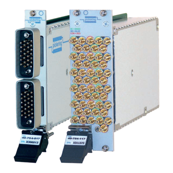
- Page 9 Windows y Supported by PXI or LXI Chassis y 3 Year Warranty The 40-754 is a 50 Ω High Density RF switch available with 17 or 9 SPDT relays in a single PXI module. The Switch 9 40-754 is available with two connector options; an SMB connector that provides a frequency range of 1.2 GHz...
- Page 10 Typical crosstalk plot for Typical isolation plot for all channels of 40-754-117 (17-off SPDT with SMB connectors) 40-754-117 (17-off SPDT with SMB connectors) 40-754 17-off SPDT RF Switch with MS-M connectors - side view pickeringtest.com 50Ω RF SPDT SWITCH MODULE 40-754...
- Page 11 SECTION 1 - TECHNICAL SPECIFICATION pickering Specifications 17off SPDT 50 Ω RF Switches, 40-754 Mechanical Characteristics - MS-M RF Connector Versions RF Specification - MS-M RF Multiway Connector Versions Single slot 3 U PXI (CompactPCI card). Impedance: 50 Ω 3D models for all versions in a variety of popular file...
-
Page 12: Technical Specification
Connection Solutions catalog. Pickering can supply cable assemblies for all its modules. The cable shown (MS-M RF to unterminated coax) is suitable for multiway connector versions of the 40-754. - Page 13 We provide a full range of supporting cable and connector solutions for all our switching products—20 connector families with 1200+ products. We offer everything from simple mating connectors to complex cables assemblies and terminal blocks. All assemblies are manufactured by Pickering and are guaranteed to mechanically and electrically mate to our modules. Connectors & Backshells...
- Page 14 17off SPDT 50 Ω RF Switches, 40-754 Programming Pickering provide kernel, IVI and VISA (NI & Keysight) drivers which are compatible with all Microsoft supported versions of Windows and popular older versions. For a list of all supporting operating systems, please see: pickeringtest.com/os...
-
Page 15: Functional Description
Compact PCI connector J1. The interface to the user test equipment is via the front panel mounted 26-pin multiway coaxial connectors (40-754-017/009) or via 51 individual SMB coaxial connectors (40-755-109). The module comprises a PCB populated with 17 high quality electro-mechanical relays arranged separate SPDT RF switches. - Page 16 SECTION 2 - TECHNICAL DESCRIPTION pickering THIS PAGE INTENTIONALLY BLANK 50Ω RF SPDT SWITCH MODULE 40-754 Page 2.2...
-
Page 17: Installation
Modular products require installation in a suitable PXI/LXI chassis. The module is designed for indoor use only. PREOPERATION CHECKS (UNPACKING) 1. Check the module for transport damage and report any damage immediately to Pickering Interfaces. Do not attempt to install the product if any damage is evident. -
Page 18: Hardware Installation
For a system comprising more than one chassis, turn ON the last chassis in the system followed by the penultimate, etc, and finally turn ON the external controller or chassis containing the system controller. 9. For Pickering Interfaces modular LXI installation there is no requirement to use any particular power up sequence. -
Page 19: Testing Operation
Figure 3.2 - General Soft Front Panel Icon A selector panel will appear, listing all installed Pickering PCI, PXI or LXI switch cards and resistor cards. Click on the card you wish to control, and a graphical control panel is presented allowing operation of the card. - Page 20 SECTION 3 - INSTALLATION pickering THIS PAGE INTENTIONALLY BLANK 50Ω RF SPDT SWITCH MODULE 40-754 Page 3.4...
-
Page 21: Programming Guide
SECTION 4 - PROGRAMMING GUIDE PROGRAMMING OPTIONS FOR PICKERING INTERFACES PXI MODULES For information on the installation and use of drivers and the programming of Pickering’s products in various software environments, please refer to the Software User Manual. This is available as a download from: https://www.pickeringtest.com/support/software-drivers-and-downloads... -
Page 22: Switch Module Architecture
SWITCH MODULE ARCHITECTURE The 40-754 modules is an array of 9 or 17 uncommitted SPDT RF relays. In the default state, all signal paths are between the C terminal and the corresponding NC terminal. Energising a particular relay breaks the C to NC connection and creates a path between the C and NO terminals. -
Page 23: Programming The Switch Module
Once the drivers are installed the manual “Sys40Prg.pdf” and driver help files which fully describes these functions can be found in the Pickering folder(s) or the Pickering entries on your Start Menu. The card must be opened before use and closed after using the following function calls: Direct I/O Driver - Open with PIL_OpenCards or PIL_OpenSpecifiedCard and close with PIL_CloseCards or PIL_CloseSpecifiedCards respectively. - Page 24 // Operates Switch 1 pi40iv_Disconnect(vi, com1, ch1); // Releases Switch 1 pi40iv_Connect(vi, com6, ch6); // Operates Switch 6 The IVI Swtch driver specification contains no bulk setting capabilities. 50Ω RF SPDT SWITCH MODULE 40-754 Page 4.4...
-
Page 25: Using Pickering Drivers In Labview
USING PICKERING DRIVERS IN LabVIEW Most Pickering drivers include a LabVIEW wrapper to permit full operation of the Pickering product from the LabVIEW environment. These wrappers are normally installed to the current LabVIEW folder system during installation of the Pickering driver. - Page 26 SECTION 4 - PROGRAMMING GUIDE pickering THIS PAGE INTENTIONALLY BLANK 50Ω RF SPDT SWITCH MODULE 40-754 Page 4.6...
-
Page 27: Connector Information
Switch 10 Switch 11 Switch 12 Switch 13 Switch 14 Switch 15 Switch 16 Switch 17 Figure 5.1 - Pinout: 40-754-017 17-off SPDT RF Switch (2-off 26-pin High Density MS-M Multipole Coaxial Connectors) 50Ω RF SPDT SWITCH MODULE 40-754 Page 5.1... - Page 28 Switch 4 Switch 5 Switch 6 Switch 7 Switch 8 Lower Connector Switch 9 Switch No Connection Figure 5.2 - Pinout: 40-754-009 9-off SPDT RF Switch (26-pin High Density MS-M Multipole Coaxial Connector) 50Ω RF SPDT SWITCH MODULE 40-754 Page 5.2...
- Page 29 Switch 9 Switch 10 Switch 11 Switch 12 Switch 13 Switch 14 Switch 15 Switch 16 Switch 17 Figure 5.3 - Connector Positioning: 40-754-117 17-off SPDT RF Switch (51-off SMB Coaxial Connectors) 50Ω RF SPDT SWITCH MODULE 40-754 Page 5.3...
- Page 30 Switch 1 Switch 2 Switch 3 Switch 4 Switch 5 Switch 6 Switch 7 Switch 8 Switch 9 Figure 5.4 - Connector Positioning: 40-754-109 9-off SPDT RF Switch (27-off SMB Coaxial Connectors) 50Ω RF SPDT SWITCH MODULE 40-754 Page 5.4...
-
Page 31: Trouble Shooting
PCI configuration, highlighting any potential configuration problems. Specific details of all installed Pickering switch cards are included. All the installed Pickering switch cards should be listed in the “Pilpxi information” section - if one or more cards is missing it may be possible to determine the reason by referring to the PCI configuration dump contained in the report, but interpretation of this information is far from straightforward, and the best course is to contact Pickering support: support@pickeringtest.com, if possible... - Page 32 SECTION 6 - TROUBLE SHOOTING pickering THIS PAGE INTENTIONALLY BLANK 50Ω RF SPDT SWITCH MODULE 40-754 Page 6.2...
-
Page 33: Maintenance Information
For PXI modules which are supported in one of Pickering Interfaces’ Modular LXI Chassis (such as the 60-102B and 60-103B) no module software update is required. If the module was introduced after the LXI chassis was manufactured the module may not be recognized, in this case the chassis firmware may need upgrading. - Page 34 SECTION 7 - MAINTENANCE INFORMATION pickering TABLE 7.1 - RF Switch Module 40-754 Relay Numbering Signal Path (with relay energised) Signal Path (with relay de-energised) Relay RF Switch Number 40-754-009 & 40-754-017 & 40-754-009 & 40-754-017 & Number On PCB...
- Page 35 SECTION 7 - MAINTENANCE INFORMATION pickering Figure 7.1 - RF Switch Module 40-754: Component Layout 50Ω RF SPDT SWITCH MODULE 40-754 Page 7.3...
- Page 36 SECTION 7 - MAINTENANCE INFORMATION pickering THIS PAGE INTENTIONALLY BLANK 50Ω RF SPDT SWITCH MODULE 40-754 Page 7.4...
Need help?
Do you have a question about the 40-754 and is the answer not in the manual?
Questions and answers