
Related Manuals for Pickering 4-190C Series


Summary of Contents for Pickering 4-190C Series
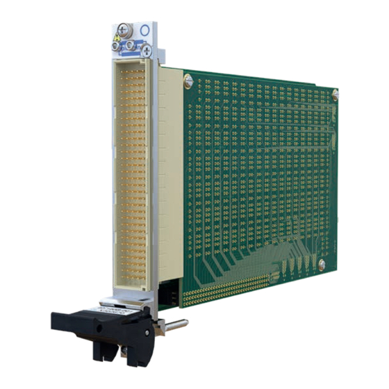
- Page 1 4x-190C User Manual PXI/PXIe 2 A Fault Insertion Switch pickeringtest.com Issue 1.1, December 2023...
- Page 2 © Copyright (2023) Pickering Interfaces. All Rights Reserved. No part of this publication may be reproduced, transmitted, transcribed, translated or stored in any form, or by any means without the written permission of Pickering Interfaces. Technical details contained within this publication are subject to change without notice.
- Page 3 Pickering Interfaces strives to fulfil all relevant environmental laws and regulations and reduce wastes and releases to the environment. Pickering Interfaces aims to design and operate products in a way that protects the environment and the health and safety of its employees, customers and the public. Pickering Interfaces endeavours to develop and manufacture products that can be produced, distributed, used and recycled, or disposed of, in a safe and environmentally friendly manner.
-
Page 4: Product Safety
Product Safety Safety Symbols The following safety symbols may be used on the product and throughout the product documentation. Meaning/Description Symbol PROTECTIVE EARTH (GROUND) To identify any terminal which is intended for connection to an external conductor for protection against electric shock in case of a fault, or the terminal of a protective earth (ground) electrode. -
Page 5: Table Of Contents
Hardware Installation ..............................3.2 Software Installation ..............................3.2 Testing Operation ................................3.3 Section 4 Programming Guide .................................4.1 Programming Options for Pickering PXI/PXIe Modules ..................4.1 Relay Cycle Counting Feature Details ........................4.1 Module Architecture ..............................4.2 Programming the Module ............................4.6 Using Pickering Drivers In LabVIEW ........................4.21 Section 5 Connector Information ..............................5.1... -
Page 6: Warnings And Cautions
Unused slots in the PXI/PXIe/LXI chassis are populated with blanking plates to prevent access to user I/O signals that may be present. Blanking panels are available to order from Pickering in a variety of slot widths. If the product is not used in this manner for example by using an extender card then additional care must be taken to avoid contact with exposed signals. - Page 7 Warnings & Cautions CAUTION - Product Documentation Symbol Suitably qualified & trained users should ensure that the accompanying documentation is fully read and understood before attempting to install or operate the product. Safety Instructions Safety Instructions All cleaning and servicing requires the equipment to be isolated and disconnected from the power source and user I/O signals (refer to the Maintenance Section).
-
Page 8: Technical Specification
PXI/PXIe 2 A Fault Insertion Switch Section 1 - Technical Specification 4x-190C y Available as PXI or PXIe Modules y 74, 64 or 32 Fault Insertion Channels y Normally Closed Through Relays y 2 Fault Insertion Buses y Suitable for Automotive/Avionics ECU Burn-in/ Endurance Test Applications y High Density Low Cost Solution y Simulation of Various Types of Electrical Fault,... - Page 9 This information could allow system connections to be revised so that signals applied to heavily used contacts are swapped with lightly used contacts to prolong the working life of the relay(s). Other Fault Insertion Switches from Pickering Pickering’s Range of PXI/PXIe Fault Insertion Switches Model Signal Fault Fault...
- Page 10 Section 1 - Technical Specification Specifications 4x-190C Relay Type RF Specification (Normally Closed Through Relays) The 4x-190C is fitted with high quality electro-mechanical Bandwidth (-3 dB): M to U Path: 20 MHz (typical) relays with palladium-ruthenium gold covered contacts. Fault Path: 7 MHz (typical) A spare relay is built onto the circuit board to allow easy Crosstalk (typical):...
- Page 11 PXIe Compliance - 42-190C We recommend that Pickering mating connectors are used with this module. They are designed to ensure there are no The module is compliant with the PXIe Specification 1.0. Local mechanical interference problems when used in a PXI chassis.
- Page 12 Pickering’s PXI switching products, simplifying servicing and reducing down-time. Product Customization Product Relay Kit Pickering modules are designed and manufactured on our 4x-190C (All versions) 91-100-001 own flexible manufacturing lines, giving complete product For further assistance, please contact the sales office.
-
Page 13: Guidance On Power Handling
It should be noted that users with a Pickering Interfaces 40-908, 40-914 or 40-918 PXI chassis mounted in accordance with the user instructions ensuring free air flow, can expect a capacity of 40 W per slot. -
Page 14: Technical Description
Section 2 - Technical Description Functional Description A functional block diagram is provided in Figure 2.1. The PXI version of the module is powered by the +3.3V, +5V & +12V supplies from the backplane via Compact PCI connector J1. The PXIe version of the module is powered by the +3.3V & +12V supplies from the connectors XJ3 &... -
Page 15: Installation
Modular products require installation in a suitable PXI/PXIe/LXI chassis. The module is designed for indoor use only. Pre-operation Checks (Unpacking) 1. Check the module for transport damage and report any damage immediately to Pickering Interfaces. Do not attempt to install the product if any damage is evident. -
Page 16: Hardware Installation
If you are not a LabVIEW user you should choose the “full” version, and once that has been installed run the LabVIEW Runtime Engine installer via the shortcut on the Programs>>Pickering menu. In the absence of LabVIEW the Runtime Engine is required to support the Pickering Test Panels application. -
Page 17: Testing Operation
Figure 3.2 - General Soft Front Panel Icon A selector panel will appear, listing all installed Pickering PCI, PXI/PXIe or LXI switch cards and resistor cards. Click on the card you wish to control, and a graphical control panel is presented allowing operation of the card. Panels can be opened simultaneously for all the installed cards. -
Page 18: Relay Cycle Counting Feature Details
Section 4 - Programming Programming options for Pickering Interfaces PXI/PXIe Modules For information on the installation and use of drivers and the programming of Pickering’s products in various software environments, please refer to the Software User Manual. This is available as a download from: pickeringtest.com/support/software-drivers-and-downloads... -
Page 19: Module Architecture
Module Architecture The Pickering 4x-190C Fault Insertion Switch is available with 74, 64 or 32 channels and with two fault buses that can be separately connected to “M” and “U” terminals. The “M” to “U” through relays default to the normally closed state. The... - Page 20 Section 4 - Programming The 4x-190C modules contain multiple sub-units and two different ways to control the UUT connection switches for each channel and the fault line conditions. However, the first Sub-unit comprises all the channels, fault buses and MUX connections.
- Page 21 Section 4 - Programming 4x-190C Sub-Unit Allocation The 4x-190C is controlled with 7 sub-units. There are 2 modes of operation embedded within the card. Mode A allows the user to control all switches within one sub-unit and Mode B partitions the switches into different sub-units with respect to their function.
- Page 22 Section 4 - Programming SOFTWARE ARCHITECTURE - DUAL FAULT BUS Figure 4.2 - Fault Insertion Switch 4x-190C Sub-Unit Allocation pickeringtest.com Page 4.5...
-
Page 23: Programming The Module
Section 4 - Programming Programming the Module Programming The 4x-190C Using a Single Sub-Unit (Mode A) Here are examples of using drivers with the 4x-190C using sub-unit 1. The examples shown are for the 4x-190C-012 (74-channel, dual bus), other versions operate in the same way but with different numbers of bits in the sub-unit. Refer to Tables 4.1, 4.2 and 4.3 for the bit usage within the sub-unit. - Page 24 Section 4 - Programming Using PIPX40 setChannelState ViUInt32 sub_unit = 1; pipx40_setChannelState(vi, sub_unit, 1, VI_ON); // Operates the channel 1 Break relay pipx40_setChannelState(vi, sub_unit, 1, VI_OFF); // Releases the channel 1 Break relay pipx40_setChannelState(vi, sub_unit, 6, VI_ON); // Operates the channel 2 Fault Bus 2 relay pipx40_setChannelState(vi, sub_unit, 228, VI_ON);...
- Page 25 Section 4 - Programming Programming The 4x-190C Using Multiple Sub-Units (Mode B) Here are examples of using drivers with the 4x-190C using sub-units 2-7. The examples shown are for the 4x-190C-012 (74-channel, dual bus), other dual bus versions operate in the same way but with different numbers of bits in the sub-units. Refer to Tables 4.4, 4.5 and 4.6 for the bit usage within each sub-unit.
- Page 26 Section 4 - Programming Using PIPX40 setChannelState ViUInt32 sub_unit = 2; // Break Relays pipx40_setChannelState(vi, sub_unit, 1, VI_ON); // Operates the channel 1 Break relay pipx40_setChannelState(vi, sub_unit, 1, VI_OFF); // Releases the channel 1 Break relay sub_unit = 4; // Fault Bus 2 pipx40_setChannelState(vi, sub_unit, 2, VI_ON);...
- Page 27 Section 4 - Programming Using pi40iv The IVI driver has no special labelling for this card and treats the array of switches as a simple array, labelling the channels using the normal com./ch labelling tags. pi40iv_Connect(vi, comB1, chB1); // Operates the channel 1 Break relay pi40iv_Disconnect(vi, comB1, chB1);...
- Page 28 Section 4 - Programming Table 4.1 - Relay/Bit Table for 4x-190C-012 (74-channel, dual bus) for Sub-Unit 1 Including IVI Channel Names Sub-Unit Function IVI Channel Names Sub-Unit Function IVI Channel Names CH1 Break comA1 chA1 CH20 Fault1 comA59 chA59 CH1 Fault1 comA2 chA2 CH20 Fault2...
- Page 29 Section 4 - Programming Table 4.1 (Continued) - Relay/Bit Table for 4x-190C-012 (74-channel, dual bus) for Sub-Unit 1 Including IVI Channel Names Sub-Unit Function IVI Channel Names Sub-Unit Function IVI Channel Names CH39 Fault2 comA117 chA117 CH59 Break comA175 chA175 CH40 Break comA118 chA118...
- Page 30 Section 4 - Programming Table 4.2 - Relay/Bit Table for 4x-190C-112 (64-channel, dual bus) for Sub-Unit 1 Including IVI Channel Names Sub-Unit Function IVI Channel Names Sub-Unit Function IVI Channel Names CH1 Break comA1 chA1 CH17 Fault2 comA51 chA51 CH1 Fault1 comA2 chA2 CH18 Break...
- Page 31 Section 4 - Programming Table 4.2 (Continued) - Relay/Bit Table for 4x-190C-112 (64-channel, dual bus) for Sub-Unit 1 Including IVI Channel Names Sub-Unit Function IVI Channel Names Sub-Unit Function IVI Channel Names CH34 Fault1 comA101 chA101 CH51 Fault1 comA152 chA152 CH34 Fault2 comA102 chA102...
- Page 32 Section 4 - Programming Table 4.3 - Relay/Bit Table for 4x-190C-212 (32-channel, dual bus) for Sub-Unit 1 Including IVI Channel Names Sub-Unit Function IVI Channel Names Sub-Unit Function IVI Channel Names CH1 Break comA1 chA1 CH18 Fault2 comA54 chA54 CH1 Fault1 comA2 chA2 CH19 Break...
- Page 33 Section 4 - Programming Table 4.4 - Relay/Bit Table for 4x-190C-012 (74-channel, dual bus) for Sub-Units 2-7 Including IVI Channel Names Sub-Unit Function IVI Channel Names Sub-Unit Function IVI Channel Names CH1 Break comB1 chB1 CH59 Break comB59 chB59 CH2 Break comB2 chB2 CH60 Break...
- Page 34 Section 4 - Programming Table 4.4 (Continued) - Relay/Bit Table for 4x-190C-012 (74-channel, dual bus) for Sub-Units 2-7 Including IVI Channel Names Sub-Unit Function IVI Channel Names Sub-Unit Function IVI Channel Names CH43 Fault1 comC43 chC43 CH27 Fault2 comD27 chD27 CH44 Fault1 comC44 chC44...
- Page 35 Section 4 - Programming Table 4.5 - Relay/Bit Table for 4x-190C-112 (64-channel, dual bus) for Sub-Units 2-7 Including IVI Channel Names Sub-Unit Function IVI Channel Names Sub-Unit Function IVI Channel Names CH1 Break comB1 chB1 CH51 Break comB51 chB51 CH2 Break comB2 chB2 CH52 Break...
- Page 36 Section 4 - Programming Table 4.5 (Continued) - Relay/Bit Table for 4x-190C-112 (64-channel, dual bus) for Sub-Units 2-7 Including IVI Channel Names Sub-Unit Function IVI Channel Names Sub-Unit Function IVI Channel Names CH37 Fault1 comC37 chC37 CH24 Fault2 comD24 chD24 CH38 Fault1 comC38 chC38...
- Page 37 Section 4 - Programming Table 4.6 - Relay/Bit Table for 4x-190C-212 (32-channel, dual bus) for Sub-Units 2-7 Including IVI Channel Names Sub-Unit Function IVI Channel Names Sub-Unit Function IVI Channel Names CH1 Break comB1 chB1 CH22 Fault1 comC22 chC22 CH2 Break comB2 chB2 CH23 Fault1...
-
Page 38: Using Pickering Drivers In Labview
Section 4 - Programming Using Pickering Drivers In LabVIEW Most Pickering drivers include a LabVIEW wrapper to permit full operation of the Pickering product from the LabVIEW environment. These wrappers are normally installed to the current LabVIEW folder system during installation of the Pickering driver. - Page 39 Section 5 - Connectors 4x-190-012 - Pinout Connector Columns A B C D E MON1 MON2 FP_GND FP_GND 160-pin Male DIN 41612 Connector (viewed from front of module) Figure 5.1 - Pinouts: 2A Fault Insertion Module 4x-190C-012 - 74-channel, dual bus pickeringtest.com Page 5.1...
- Page 40 Section 5 - Connectors 4x-190-112 - Pinout Connector Columns A B C D E – – – – – – – – – – – – – – – – MON1 – – – – MON2 FP_GND FP_GND 160-pin Male DIN 41612 Connector (viewed from front of module) Figure 5.2 - Pinouts: 2A Fault Insertion Module 4x-190C-112 - 64-channel, dual bus pickeringtest.com...
- Page 41 Section 5 - Connectors 4x-190-212 - Pinout Connector Columns A B C D E – – – – – – – – – – – – – – – – – – – – – – – – – – –...
-
Page 42: Trouble Shooting
PCI configuration, highlighting any potential configuration problems. Specific details of all installed Pickering switch cards are included. All the installed Pickering switch cards should be listed in the “Pilpxi information” section - if one or more cards is missing it may be possible to determine the reason by referring to the PCI configuration dump contained in the report, but interpretation of this information is far from straightforward, and the support@pickeringtest.com... -
Page 43: Maintenance Information
For PXI modules which are supported in one of Pickering Interfaces’ Modular LXI Chassis (such as the 60-102B and 60-103B) no module software update is required. If the module was introduced after the LXI chassis was manufactured the module may not be recognized, in this case the chassis firmware may need upgrading. - Page 44 Section 7 - Maintenance Information Relay Look-up Tables The following tables cross-reference the 4x-190C module’s output signals to the physical relays on the mother board and daughter board. This is for fault finding purposes and should be used in conjunction with the PCB layout diagrams in Figures 7.1 and 7.2.
- Page 45 Section 7 - Maintenance Information Relay Look-up Table - 4x-190C Motherboard - Continued 4x-190C- 4x-190C- 4x-190C- 4x-190C- 4x-190C- 4x-190C- Function Relay Function Relay CH25 Break RL74 CH30 Fault2 RL85 ✔ ✔ ✔ ✔ ✔ ✔ CH25 Fault1 RL75 CH31 Break RL92 ✔...
- Page 46 Section 7 - Maintenance Information Relay Look-up Table - 4x-190C Daughterboard 4x-190C- 4x-190C- 4x-190C- 4x-190C- 4x-190C- 4x-190C- Function Relay Function Relay CH33 Break RL98 CH48 Break RL143 ✔ ✔ ✔ ✔ CH33 Fault1 RL99 CH48 Fault1 RL144 ✔ ✔ ✔ ✔...
- Page 47 Section 7 - Maintenance Information Relay Look-up Table - 4x-190C Daughterboard - Continued 4x-190C- 4x-190C- 4x-190C- 4x-190C- 4x-190C- 4x-190C- Function Relay Function Relay CH63 Break RL188 CH69 Break RL206 ✔ ✔ ✔ CH63 Fault1 RL189 CH69 Fault1 RL207 ✔ ✔ ✔...
Need help?
Do you have a question about the 4-190C Series and is the answer not in the manual?
Questions and answers