
Related Manuals for Pickering 40-860


Summary of Contents for Pickering 40-860
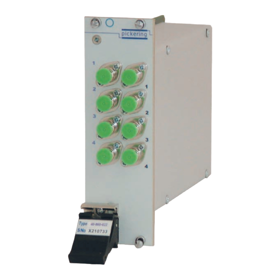
- Page 1 40-860 User Manual PXI MEMS Fiber Optic Insert/Bypass Switch Module pickeringtest.com Issue 4.2 May 2021...
- Page 2 © COPYRIGHT (2021) PICKERING INTERFACES. ALL RIGHTS RESERVED. No part of this publication may be reproduced, transmitted, transcribed, translated or stored in any form, or by any means without the written permission of Pickering Interfaces. Technical details contained within this publication are subject to change without notice.
- Page 3 Pickering Interfaces strives to fulfil all relevant environmental laws and regulations and reduce wastes and releases to the environment. Pickering Interfaces aims to design and operate products in a way that protects the environment and the health and safety of its employees, customers and the public. Pickering Interfaces endeavours to develop and manufacture products that can be produced, distributed, used and recycled, or disposed of, in a safe and environmentally friendly manner.
-
Page 4: Product Safety
This product is capable of switching laser optical signals. STATIC SENSITIVE To indicate that static sensitive devices are present and handling precautions should be followed. REED RELAY MODULE 40-110/115/120/125 MEMS FIBER OPTIC INSERT/BYPASS SWITCH MODULE 40-860 Page (IV) Page (IV) -
Page 5: Table Of Contents
Programming Options For Pickering PXI Modules ....4.1 Module Architecture ..............4.2 Programming The Module ............4.3 Section 5 Connector Information ..............5.1 Section 6 Trouble Shooting .................6.1 Section 7 Maintenance Information ............7.1 Relay Lookup Tables / Component Layout ......7.1 MEMS FIBER OPTIC INSERT/BYPASS SWITCH MODULE 40-860 Page (V) - Page 6 THIS PAGE INTENTIONALLY BLANK MEMS FIBER OPTIC INSERT/BYPASS SWITCH MODULE 40-860 Page (VI)
-
Page 7: Warnings And Cautions
Unused slots in the PXI/LXI chassis are populated with blanking plates to prevent access to user I/O signals that may be present. Blanking panels are available to order from Pickering in a variety of slot widths. If the product is not used in this manner for example by using an extender card then additional care must be taken to avoid contact with exposed signals. - Page 8 I/O ports. • For suitably equipped products in the event of an emergency press the red “emergency stop” button situated on the front of the unit. MEMS FIBER OPTIC INSERT/BYPASS SWITCH MODULE 40-860 REED RELAY MODULE 40-110/115/120/125 Page (VIII)
- Page 9 The range of MEMS (Micro-Electro-Mechanical-Systems) Applications based optical switches is: • Optical signal routing • 40-860-X12 – Single 2x2 Insert/Bypass Switch • Fiber network configuration • 40-860-X22 – Dual 2x2 Insert/Bypass Switch • Fiber Optic Component Test • 40-860-X32 – Triple 2x2 Insert/Bypass Switch •...
- Page 10 All modules are fully CE compliant and meet applicable EU directives: Low-voltage safety EN61010-1:2010, EMC Immunity EN61326-1:2013, Emissions EN55011:2009+A1:2010. Pickering Interfaces Will Configure PXI Optical Switching Systems To Customers Exact Requirements Including Custom Cabling pickeringtest.com MEMS FIBER OPTIC INSERT/BYPASS SWITCH MODULE 40-860 Page 1.2...
- Page 11 Ordering Information Optical Insert/Bypass Switch, 40-860 Product Order Codes Product Customization Pickering modules are designed and manufactured on our 2x2 Insert/Bypass Switch Versions own flexible manufacturing lines, giving complete product FC/APC, 1240 to 1640 nm, Single-Mode control and enabling simple customization to meet very...
- Page 12 We provide a full range of supporting cable and connector solutions for all our switching products—20 connector families with 1200+ products. We offer everything from simple mating connectors to complex cables assemblies and terminal blocks. All assemblies are manufactured by Pickering and are guaranteed to mechanically and electrically mate to our modules. Connectors & Backshells...
- Page 13 Optical Insert/Bypass Switch, 40-860 Programming Pickering provide kernel, IVI and VISA (NI & Keysight) drivers which are compatible with all Microsoft supported versions of Windows and popular older versions. For a list of all supporting operating systems, please see: pickeringtest.com/os The VISA driver is also compatible with Real-Time Operating Systems such as LabVIEW RT.
- Page 14 SECTION 1 - TECHNICAL SPECIFICATION pickering THIS PAGE INTENTIONALLY BLANK MEMS FIBER OPTIC INSERT/BYPASS SWITCH MODULE 40-860 Page 1.6...
-
Page 15: Functional Description
FUNCTIONAL DESCRIPTION Functional block diagrams for the single and dual versions of the 40-860 are provided in Figures 2.1 and 2.2. The Fiber Insert/Bypass Module is powered by a +5V input via Compact PCI connector J1. The module comprises one or two fiber optic insert/bypass switches which connect two optical channel inputs to two corresponding outputs. - Page 16 SECTION 2 - TECHNICAL DESCRIPTION pickering THIS PAGE INTENTIONALLY BLANK MEMS FIBER OPTIC INSERT/BYPASS SWITCH MODULE 40-860 Page 2.2...
-
Page 17: Installation
Modular products require installation in a suitable PXI/LXI chassis. The module is designed for indoor use only. PREOPERATION CHECKS (UNPACKING) 1. Check the module for transport damage and report any damage immediately to Pickering Interfaces. Do not attempt to install the product if any damage is evident. -
Page 18: Hardware Installation
For a system comprising more than one chassis, turn ON the last chassis in the system followed by the penultimate, etc, and finally turn ON the external controller or chassis containing the system controller. 9. For Pickering Interfaces modular LXI installation there is no requirement to use any particular power up sequence. -
Page 19: Testing Operation
Figure 3.2 - General Soft Front Panel Icon A selector panel will appear, listing all installed Pickering PCI, PXI or LXI switch cards and resistor cards. Click on the card you wish to control, and a graphical control panel is presented allowing operation of the card. - Page 20 SECTION 3 - INSTALLATION pickering THIS PAGE INTENTIONALLY BLANK MEMS FIBER OPTIC INSERT/BYPASS SWITCH MODULE 40-860 Page 3.4...
-
Page 21: Programming Guide
SECTION 4 - PROGRAMMING GUIDE PROGRAMMING OPTIONS FOR PICKERING INTERFACES PXI MODULES For information on the installation and use of drivers and the programming of Pickering’s products in various software environments, please refer to the Software User Manual. This is available as a download from: https://www.pickeringtest.com/support/software-drivers-and-downloads... -
Page 22: Module Architecture
Channel 7 MODULE ARCHITECTURE 40-860 The 40-860 Modules utilise one or more MEMS switches depending on the option. In the default state the Channels Channel 8 selected are 1 to 3 and 2 to 4. Energising the MEMS switch appropriately switches the signal paths to the other output terminals. -
Page 23: Programming The Module
PROGRAMMING THE MODULE 40-860 Here are some simple examples of using the drivers with the 40-860 Insert/Bypass Switch Module. Channels 1 to 3 and 2 to 4 are the defaults. The Dual 2 Channel Switch Modules operate in the similar way but have a different number of bits in the sub-unit. - Page 24 SECTION 4 - PROGRAMMING GUIDE pickering THIS PAGE INTENTIONALLY BLANK MEMS FIBER OPTIC INSERT/BYPASS SWITCH MODULE 40-860 Page 4.4...
- Page 25 SECTION 5 - CONNECTOR INFORMATION Channel 7 Channel 8 Figure 5.1 provides pin-outs for the Fiber Optic Insert/Bypass Modules in the 40-860 single switch range, Figure 5.2 provides pin-outs for the Fiber Optic Insert/Bypass Modules in the 40-860 dual switch range. Reset State...
- Page 26 2 Channel Insert/Bypass Switch 1 2 Channel Insert/Bypass Switch 2 pickering pickering pickering pickering pickering 40-860-022/122 40-860-222 40-860-322 40-860-422 40-860-522-M 40-860-222-M Figure 5.2 - Dual Fiber Optic Insert/Bypass Switch Module 40-860: Connector Positions MEMS FIBER OPTIC INSERT/BYPASS SWITCH MODULE 40-860 Page 5.2...
-
Page 27: Trouble Shooting
PCI configuration, highlighting any potential configuration problems. Specific details of all installed Pickering switch cards are included. All the installed Pickering switch cards should be listed in the “Pilpxi information” section - if one or more cards is missing it may be possible to determine the reason by referring to the PCI configuration dump contained in the report, but interpretation of this information is far from straightforward, and the best course is to contact Pickering support: support@pickeringtest.com, if possible... - Page 28 SECTION 6 - TROUBLE SHOOTING pickering THIS PAGE INTENTIONALLY BLANK MEMS FIBER OPTIC INSERT/BYPASS SWITCH MODULE 40-860 Page 6.2...
-
Page 29: Maintenance Information
For PXI modules which are supported in one of Pickering Interfaces’ Modular LXI Chassis (such as the 60-102B and 60-103B) no module software update is required. If the module was introduced after the LXI chassis was manufactured the module may not be recognized, in this case the chassis firmware may need upgrading. - Page 30 SECTION 7 - MAINTENANCE INFORMATION pickering Table 7.1 - Fiber Optic Insert/Bypass Switch Module 40-860: Relay Numbering Board Relay No. Signal Path 40-860-012 Channel 1 to Channel 3 Default Channel 2 to Channel 4 Channel 1 to Channel 4 Energised...
- Page 31 SECTION 7 - MAINTENANCE INFORMATION pickering Table 7.2 - Dual Fiber Optic Insert/Bypass Switch Module 40-860: Relay Numbering Board Relay Nos. Bank Signal Path 40-860-022/122/122 Channel 1 to Channel 3 Default Channel 2 to Channel 4 Channel 1 to Channel 4...
- Page 32 SECTION 7 - MAINTENANCE INFORMATION pickering THIS PAGE INTENTIONALLY BLANK MEMS FIBER OPTIC INSERT/BYPASS SWITCH MODULE 40-860 Page 7.4...
Need help?
Do you have a question about the 40-860 and is the answer not in the manual?
Questions and answers