
Related Manuals for Pickering 41-735


Summary of Contents for Pickering 41-735
- Page 1 41-735/736 User Manual PXI Programmable Power Supply Module pickeringtest.com Issue 6.6 October 2022...
- Page 2 © COPYRIGHT (2022) PICKERING INTERFACES. ALL RIGHTS RESERVED. No part of this publication may be reproduced, transmitted, transcribed, translated or stored in any form, or by any means without the written permission of Pickering Interfaces. Technical details contained within this publication are subject to change without notice.
- Page 3 Pickering Interfaces strives to fulfil all relevant environmental laws and regulations and reduce wastes and releases to the environment. Pickering Interfaces aims to design and operate products in a way that protects the environment and the health and safety of its employees, customers and the public. Pickering Interfaces endeavours to develop and manufacture products that can be produced, distributed, used and recycled, or disposed of, in a safe and environmentally friendly manner.
-
Page 4: Product Safety
If this product is heavy reference should be made to the safety instructions for provisions of lifting and moving. STATIC SENSITIVE To indicate that static sensitive devices are present and handling precautions should be followed. REED RELAY MODULE 40-110/115/120/125 PROGRAMMABLE POWER SUPPLY MODULE 41-735/736 Page iv Page (IV) -
Page 5: Table Of Contents
Hardware Installation ........... 3.1 Soft Front Panel Installation ........3.2 Soft Front Panel Operation .......... 3.3 Section 4 Programming Guide ............4.1 Programming Options For Pickering PXI Modules ... 4.1 Card Specific Information ..........4.3 Section 5 Connector Information ............5.1 Section 6 Trouble Shooting .............. - Page 6 THIS PAGE INTENTIONALLY BLANK PROGRAMMABLE POWER SUPPLY MODULE 41-735/736 Page vi...
-
Page 7: Technical Specification
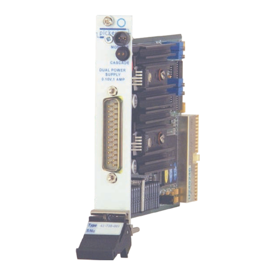
Plus Soft Front Panel y Supported in PXI or LXI Chassis y 3 Year Warranty The 41-735 is a single slot power supply module providing two programmable positive output voltages. The module produces high quality regulated voltages from a linear regulator to ensure low levels of output noise. - Page 8 Time / µs Time / µs 6.1V (0.8A - 0.4A) 7.5V (0.4A - 0.8A) Trigger Pulse Trigger Pulse Transient Response Plots For 41-735 Power Supply Module Block Diagram for 41-735 Power Supply Module pickeringtest.com Page 1.2 PROGRAMMABLE POWER SUPPLY MODULE 41-735/736...
- Page 9 SECTION 1 - TECHNICAL SPECIFICATION pickering Specifications Dual +10V Power Supply, 41-735 Specification Output Voltage: 0 to +10V, o/p is referenced Leakage Monitor: Allows the measurement of to GND. leakage current. Maximum current is 10µA. Accuracy Remote Sense: Provided on positive ±2% ±3nA...
- Page 10 Dual +10V Power Supply, 41-735 Product Order Codes Mating Connectors & Cabling Dual Programmable +10V Power Supply 41-735-001 For connection accessories for the 41-735 module please refer to the 90-008D 25-pin D-type Connector Accessories Product Customization data sheet where a complete list and documentation...
- Page 11 DMM. The 16-bit setting resolution of the output voltage combined with the accurate monitoring facility is perfect for characterizing device performance as a function of supply voltage. 41-736 Soft Front Panel pickeringtest.com Page 1.5 PROGRAMMABLE POWER SUPPLY MODULE 41-735/736...
- Page 12 Safety & CE Compliance Power Requirements All modules are fully CE compliant and meet +3.3V +12V -12V applicable EU directives: Low-voltage safety EN61010- 0.15A 0.05A Up to 1A 1:2010, EMC Immunity EN61326-1:2013, Emissions EN55011:2009+A1:2010.* pickeringtest.com Page 1.6 PROGRAMMABLE POWER SUPPLY MODULE 41-735/736...
- Page 13 25-pin D-type Connector Accessories Product Customization data sheet where a complete list and documentation Pickering modules are designed and manufactured on our can be found for accessories, or refer to the Connection own flexible manufacturing lines, giving complete product Solutions catalog.
- Page 14 We provide a full range of supporting cable and connector solutions for all our switching products—20 connector families with 1200+ products. We offer everything from simple mating connectors to complex cables assemblies and terminal blocks. All assemblies are manufactured by Pickering and are guaranteed to mechanically and electrically mate to our modules. Connectors & Backshells...
-
Page 15: Technical Description
Dual -10V Power Supply, 41-736 Programming Pickering provide kernel, IVI and VISA (NI & Keysight) drivers which are compatible with all Microsoft supported versions of Windows and popular older versions. For a list of all supporting operating systems, please see: pickeringtest.com/os... - Page 16 SECTION 2 - TECHNICAL DESCRIPTION pickering THIS PAGE INTENTIONALLY BLANK Page 2.10 PROGRAMMABLE POWER SUPPLY MODULE 41-735/736...
-
Page 17: Functional Description
A functional block diagram is provided in Figure 2.1. The 41-735/736 Programmable Power Supply Module is a non-isolated power supply using linear regulators, which are powered via the PXI chassis +12 V supply. For applications where the current drawn exceeds 1 Amp the power supply can draw power from an alternative external power supply connected to the front panel connector. - Page 18 If the monitor circuit closes down the supply the supply should be turned off, the fault cleared and then normal operation can resume. The monitoring circuit is not used if the 41-735/736 module has DC power supplied from an external source.
-
Page 19: Cascading Monitor Ports
DMM that is likely to be part of most test systems. Some applications may require more than one 41-735/736 to be supported, or to allow other modules with similar monitor ports to be connected. - Page 20 The monitor port can be set to a cascade path where the input (from the DMM) is looped directly to the output (cascade) with no connection to internal parts of the 41-735/736, allowing modules to be connected in series. Page 2.4...
-
Page 21: Installation
Modular products require installation in a suitable PXI/LXI chassis. The module is designed for indoor use only. PREOPERATION CHECKS (UNPACKING) 1. Check the module for transport damage and report any damage immediately to Pickering Interfaces. Do not attempt to install the product if any damage is evident. -
Page 22: Hardware Installation
For a system comprising more than one chassis, turn ON the last chassis in the system followed by the penultimate, etc, and finally turn ON the external controller or chassis containing the system controller. 9. For Pickering Interfaces modular LXI installation there is no requirement to use any particular power up sequence. -
Page 23: Soft Front Panel Installation
To run the SFP choose ‘41-735/41-736 Soft Front Panel’ (shortcut to ‘41-735_Panel.exe’ ) from your Start/Programs menu (the default programs menu location is ‘Programs \ Pickering \ 41-735 \ 41-735 Soft Front Panel’ ). As the program starts it will check for the correct driver, if it doesn’t exist an error message will be shown. Once the SFP is running the desired PSU card must be selected from the Card Config menu. -
Page 24: Soft Front Panel Operation
The ‘Card Config’ menu item has a sub-item ‘Cards’ which contains two sub-menu items, ‘Available Cards’ and ‘Select Card’. Before the utility can be used any 41-735/736 cards installed in the system must be found by using the ‘Card Config | Cards | Available Cards’ menu item to access the card database window. - Page 25 When in ‘Chassis’ mode the ‘Chassis Supply Current Limit’ indicator becomes enabled to show the status of the over- current protection mechanism built into the 41-735/736 card that protects the chassis +12V supply from excessive current loads. When this indicator is green the current load is at an acceptable level, but when the indicator turns red it shows that the current draw exceeds the set limit and the output is shutdown.
- Page 26 PSU MODES Each of the two PSU channels on the 41-735/736 card has two modes of operation, ‘Normal’ and ‘Leakage’ modes. The mode is selected by clicking on either of the two small green buttons labeled ‘Normal Mode’ and ‘Leakage Mode’.
-
Page 27: Programming Guide
SECTION 4 - PROGRAMMING GUIDE PROGRAMMING OPTIONS FOR PICKERING INTERFACES PXI MODULES For information on the installation and use of drivers and the programming of Pickering’s products in various software environments, please refer to the Software User Manual. This is available as a download from: https://www.pickeringtest.com/support/software-drivers-and-downloads... -
Page 28: Card Specific Information
DIRECT I/O (KERNEL) DRIVER The 41-735/736 module can be accessed using the Direct I/O driver (Pilpxi.dll) version 2.26 or above. The functions unique to power supply type modules are documented below, but the driver is fully documented by ReadMe and HTML help files, accessible through shortcuts on the Programs>>Pickering menu once the drivers are installed. - Page 29 SECTION 4 - PROGRAMMING GUIDE pickering POWER SUPPLY FUNCTIONS Please refer to the Pickering Pilpxi driver help files for a full list functions for this card and general card programming advice. Specific functions are provided to: • Obtain power supply description, in string format: PIL_PsuType •...
- Page 30 The result is the nominal value to which the output has been set, not necessarily the actual voltage being output (which may be affected by device tolerances, current-limit conditions etc.). This function is also usable with fixed-voltage supplies, returning the nominal output voltage. PROGRAMMABLE POWER SUPPLY MODULE 41-735/736 Page 4.4...
- Page 31 0x00000002 - PSU_CAP_OUTPUT_SENSE (has logic-level sensing of output active state) 0x00000001 - PSU_CAP_OUTPUT_CONTROL (has output on/off control) Certain driver functions are only usable with sub-units having appropriate capabilities - examples being: PIL_PsuEnable PIL_PsuSetVoltage PROGRAMMABLE POWER SUPPLY MODULE 41-735/736 Page 4.5...
- Page 32 Zero for success, or non-zero error code. Result For a DC power supply the format of the result is “PSUDC(<rated voltage>,<rated current>)”. Note More detailed information on power supply characteristics is obtainable in numeric format, using PIL_PsuInfo. PROGRAMMABLE POWER SUPPLY MODULE 41-735/736 Page 4.6...
- Page 33 (front panel connector V+ to GND) Measure load voltage RL16 Measures voltage at the RL23 load (V+ sense line to V- sense line) Measure output current RL14 (voltage reading to be RL21 scaled to current) PROGRAMMABLE POWER SUPPLY MODULE 41-735/736 Page 4.7...
- Page 34 Logical sub unit Logical Switch Measure Leakage Current RL15 RL22 Table 4.8 - Channel 2 Measurement Leakage Mode Monitor Port Function Relays ON Logical sub unit Logical Switch Measure Leakage Current RL19 RL25 PROGRAMMABLE POWER SUPPLY MODULE 41-735/736 Page 4.8...
- Page 35 Setting External Power Source The normal operating condition for the 41-735 module is to use the PXI backplane as its power source. For some applications the user may wish to use an external power source. This is achieved by control of RL1 (Logical sub unit 8, logical switch 1) which should be set to closed for an external power source.
- Page 36 SECTION 4 - PROGRAMMING GUIDE pickering THIS PAGE INTENTIONALLY BLANK PROGRAMMABLE POWER SUPPLY MODULE 41-735/736 Page 4.10...
- Page 37 Vout_CH2 GND_Sense_CH2 Vout_Sense_CH2 Vout_CH2 -ve GND_Sense_CH2 -ve Vout_Sense_CH2-ve Monitor- Monitor- Monitor+ Monitor+ Cascade Monitor- Cascade Monitor- Cascade Monitor+ Cascade Monitor+ EXT+V EXT-V 41-736 41-735 Figure 5.1 - Programmable Power Supply: Front Panel Connectors Page 5.1 PROGRAMMABLE POWER SUPPLY MODULE 41-735/736...
- Page 38 SECTION 5 - CONNECTOR INFORMATION pickering THIS PAGE INTENTIONALLY BLANK Page 5.2 PROGRAMMABLE POWER SUPPLY MODULE 41-735/736...
-
Page 39: Trouble Shooting
PCI configuration, highlighting any potential configuration problems. Specific details of all installed Pickering switch cards are included. All the installed Pickering switch cards should be listed in the “Pilpxi information” section - if one or more cards is missing it may be possible to determine the reason by referring to the PCI configuration dump contained in the report, but interpretation of this information is far from straightforward, and the best course is to contact Pickering support: support@pickeringtest.com, if possible... - Page 40 SECTION 6 - TROUBLE SHOOTING pickering THIS PAGE INTENTIONALLY BLANK Page 6.2 PROGRAMMABLE POWER SUPPLY MODULE 41-735/736...
-
Page 41: Maintenance Information
For PXI modules which are supported in one of Pickering Interfaces’ Modular LXI Chassis (such as the 60-102B and 60-103B) no module software update is required. If the module was introduced after the LXI chassis was manufactured the module may not be recognized, in this case the chassis firmware may need upgrading. - Page 42 The number of DMM can be reduced to one by switching external or by manual transfer between the two points. Use the supplied soft front panel to control the 41-735/736 module, or any suitable software interface the user has created.
- Page 43 Zero the DMM 1 with the dummy monitor resistor selected through the SFP, then reset to leakage mode. Measure the voltage on DMM 2 which should be 100 nA * 10 k 1 mV to an accuracy of (+/-2% +/-3 nA) Page 7.3 PROGRAMMABLE POWER SUPPLY MODULE 41-735/736...
- Page 44 Apply a 100 ohm load across the output. Check that the output voltage is less than 0.5 V Turn Channel 1 off, then set the 41-735/736 module to external power source and apply a +12 V external source voltage. Turn Channel 1 on and check the output voltage can now be wet to 5 V.
-
Page 45: Component Layout
SECTION 7 - MAINTENANCE INFORMATION pickering COMPONENT LAYOUT The component Layout is as detailed in Figures 7.1 and 7.2. Figure 7.1 - Programmable Power Supply Module Figure 7.2 - Programmable Power Supply Module: Component Layout Page 7.5 PROGRAMMABLE POWER SUPPLY MODULE 41-735/736... - Page 46 SECTION 7 - MAINTENANCE INFORMATION pickering THIS PAGE INTENTIONALLY BLANK Page 7.6 PROGRAMMABLE POWER SUPPLY MODULE 41-735/736...
Need help?
Do you have a question about the 41-735 and is the answer not in the manual?
Questions and answers