
Related Manuals for Pickering 41-761


Summary of Contents for Pickering 41-761
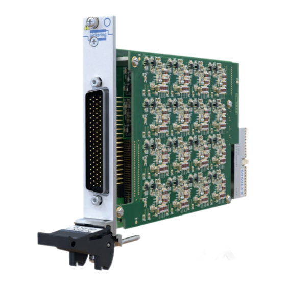
- Page 1 41-761 User Manual PXI Isolated Millivolt Thermocouple Simulator Module pickeringtest.com Issue 1.0 December 2019...
- Page 2 © COPYRIGHT (2019) PICKERING INTERFACES. ALL RIGHTS RESERVED. No part of this publication may be reproduced, transmitted, transcribed, translated or stored in any form, or by any means without the written permission of Pickering Interfaces. Technical details contained within this publication are subject to change without notice.
- Page 3 Pickering Interfaces strives to fulfil all relevant environmental laws and regulations and reduce wastes and releases to the environment. Pickering Interfaces aims to design and operate products in a way that protects the environment and the health and safety of its employees, customers and the public. Pickering Interfaces endeavours to develop and manufacture products that can be produced, distributed, used and recycled, or disposed of, in a safe and environmentally friendly manner.
- Page 4 If this product is heavy reference should be made to the safety instructions for provisions of lifting and moving. STATIC SENSITIVE To indicate that static sensitive devices are present and handling precautions should be followed. ISOLATED MILLIVOLT THERMOCOUPLE SIMULATOR 41-761 Page iv REED RELAY MODULE 40-110/115/120/125 Page (IV)
-
Page 5: Table Of Contents
Software Installation ............ 3.2 Testing Operation ............3.3 Section 4 Programming Guide ............4.1 Programming Options For Pickering PXI Cards..4.1 Programming The 41-761..........4.2 General Soft Front Panel ..........4.4 Appendix: Sub-Units & Bit Usage ....... 4.5 Section 5 Connector Information ............ - Page 6 THIS PAGE INTENTIONALLY BLANK ISOLATED MILLIVOLT THERMOCOUPLE SIMULATOR 41-761 Page vi...
- Page 7 • Kernel and VISA Drivers • 3 Year Warranty The 41-761 is a low voltage output module ideal for simulating the operation of a thermocouple, available with a choice of 32, 24, 16 or 8 channels. Each channel of the 41-761 provides a low voltage output across two connector pins capable of providing ±20mV with...
- Page 8 All modules are fully CE compliant and meet applicable EU 270mA 1.4A directives: Low-voltage safety EN61010-1:2010, EMC Immunity EN61326-1:2013, Emissions EN55011:2009+A1:2010.* 41-761 Channel 1 Vcold1 Channel 2 Vcold2 Vo32 Channel 32 Vcold32 Using 41-761-001 directly connected to UUT for Thermocouple Simulation pickeringtest.com Page 1.2 ISOLATED MILLIVOLT THERMOCOUPLE SIMULATOR 41-761...
- Page 9 1m length* A078DFR-16M002T5A100 Product Customization 78-pin D-type to 8 mini copper Pickering PXI modules are designed and manufactured on our own thermocouple plugs, 1m length* A078DFR-08M002T5A100 flexible manufacturing lines, giving complete product control and *Other lengths are available.
- Page 10 We provide a full range of supporting cable and connector solutions for all our switching products—20 connector families with 1200+ products. We offer everything from simple mating connectors to complex cables assemblies and terminal blocks. All assemblies are manufactured by Pickering and are guaranteed to mechanically and electrically mate to our modules. Connectors & Backshells...
- Page 11 Isolated Thermocouple Simulator – 41-761 Programming Pickering provide kernel, IVI and VISA (NI & Keysight) drivers which are compatible with all Microsoft supported versions of Windows and popular older versions. For a list of all supporting operating systems, please see: pickeringtest.com/os...
- Page 12 SECTION 1 - TECHNICAL SPECIFICATION pickering THIS PAGE INTENTIONALLY BLANK Page 1.6 ISOLATED MILLIVOLT THERMOCOUPLE SIMULATOR 41-761...
-
Page 13: Functional Description
Translators Logic Ux13 U1 to U6 Power Convertors DCx1 +3.3V Figure 2.1 - Isolated Millivolt Thermocouple Simulator 41-761: Functional Block Diagram 780µs Figure 2.2 - Voltage Change: 100mV to -100mV High Range 780µs Page 2.1 ISOLATED MILLIVOLT THERMOCOUPLE SIMULATOR 41-761... - Page 14 Figure 2.3 - Voltage Change: 0mV to 100mV 3.7ms Auto Range Figure 2.4 - Voltage Change: 15mV to 45mV to 100mV 4ms per operation Auto Range 800µs Figure 2.5 - Voltage Change: -100mV to 100mV 800µs Auto Range Page 2.2 ISOLATED MILLIVOLT THERMOCOUPLE SIMULATOR 41-761...
-
Page 15: Guidance On Using The Module
GUIDANCE ON USING THE MODULE The 41-761 behaves as a precise but adjustable low voltage source, making it ideal for Thermocouple Simulation. As well as Thermocouple Simulation, it can be used for applications that require a reference voltage with fine adjustment, with high accuracy and stability. - Page 16 Figure 2.3 - Using The 41-761 Connected Directly To The UUT For Thermocouple Simulation Isolation Switches The 41-761 isolation switches on each channel provide the ability to disconnect the channels from the UUT, providing the benefit of not requiring the removal of cabling when wanting to isolate the UUT.
-
Page 17: Installation
Modular products require installation in a suitable PXI/LXI chassis. The module is designed for indoor use only. PREOPERATION CHECKS (UNPACKING) 1. Check the module for transport damage and report any damage immediately to Pickering Interfaces. Do not attempt to install the product if any damage is evident. -
Page 18: Hardware Installation
For a system comprising more than one chassis, turn ON the last chassis in the system followed by the penultimate, etc, and finally turn ON the external controller or chassis containing the system controller. 9. For Pickering Interfaces modular LXI installation there is no requirement to use any particular power up sequence. -
Page 19: Testing Operation
Figure 3.2 - General Soft Front Panel Icon A selector panel will appear, listing all installed Pickering PCI, PXI or LXI switch cards and resistor cards. Click on the card you wish to control, and a graphical control panel is presented allowing operation of the card. - Page 20 SECTION 3 - INSTALLATION pickering THIS PAGE INTENTIONALLY BLANK Page 3.4 ISOLATED MILLIVOLT THERMOCOUPLE SIMULATOR 41-761...
-
Page 21: Programming Guide
SECTION 4 - PROGRAMMING GUIDE PROGRAMMING OPTIONS FOR PICKERING INTERFACES PXI MODULES For information on the installation and use of drivers and the programming of Pickering’s products in various software environments, please refer to the Software User Manual. This is available as a download from: https://www.pickeringtest.com/support/software-drivers-and-downloads... -
Page 22: Programming The 41-761
The sub-unit usage for each version of the 41-761 is sumarized in Table 4.1. For detailed sub-unit and bit usage tables, refer to the Appendix at the end of this section. - Page 23 = PIL_OpBit(card, IsoSub , 1, 1); //Turn Vo1 on err = PIL_OpBit(card, IsoSub , 2, 1); //Turn Vcold1 on err = PIL_OpBit(card, IsoSub , 3, 1); //Turn Vo2 on err = PIL_OpBit(card, IsoSub , 1, 0); //Turn Vo1 off ISOLATED MILLIVOLT THERMOCOUPLE SIMULATOR 41-761 Page 4.3...
-
Page 24: General Soft Front Panel
Similar to our drivers, our soft front panels cover all our cards and dedicated displays are provided for some of our products as shown in the following image. Figure 4.1 - Soft Front Panel For The 41-761 Module ISOLATED MILLIVOLT THERMOCOUPLE SIMULATOR 41-761... - Page 25 Voltage Source 24 — Voltage Source 25 — Voltage Source 26 — Voltage Source 27 — Voltage Source 28 — Voltage Source 29 — Voltage Source 30 — Voltage Source 31 — Voltage Source 32 ISOLATED MILLIVOLT THERMOCOUPLE SIMULATOR 41-761 Page 4.5...
- Page 26 Vcold28 isolation Vo13 isolation Vo29 isolation Vcold13 isolation Vcold29 isolation Vo14 isolation Vo30 isolation Vcold14 isolation Vcold30 isolation Vo15 isolation Vo31 isolation Vcold15 isolation Vcold31 isolation Vo16 isolation Vo32 isolation Vcold16 isolation Vcold32 isolation ISOLATED MILLIVOLT THERMOCOUPLE SIMULATOR 41-761 Page 4.6...
- Page 27 Voltage Source 16 — Voltage Source 17 — Voltage Source 18 — Voltage Source 19 — Voltage Source 20 — Voltage Source 21 — Voltage Source 22 — Voltage Source 23 — Voltage Source 24 ISOLATED MILLIVOLT THERMOCOUPLE SIMULATOR 41-761 Page 4.7...
- Page 28 Vcold24 isolation Vo9 isolation Vcold9 isolation Vo10 isolation Vcold10 isolation Vo11 isolation Vcold11 isolation Vo12 isolation Vcold12 isolation Vo13 isolation Vcold13 isolation Vo14 isolation Vcold14 isolation Vo15 isolation Vcold15 isolation Vo16 isolation Vcold16 isolation ISOLATED MILLIVOLT THERMOCOUPLE SIMULATOR 41-761 Page 4.8...
- Page 29 Voltage Source 8 — Voltage Source 9 — Voltage Source 10 — Voltage Source 11 — Voltage Source 12 — Voltage Source 13 — Voltage Source 14 — Voltage Source 15 — Voltage Source 16 ISOLATED MILLIVOLT THERMOCOUPLE SIMULATOR 41-761 Page 4.9...
- Page 30 Vcold8 isolation Vo9 isolation Vcold9 isolation Vo10 isolation Vcold10 isolation Vo11 isolation Vcold11 isolation Vo12 isolation Vcold12 isolation Vo13 isolation Vcold13 isolation Vo14 isolation Vcold14 isolation Vo15 isolation Vcold15 isolation Vo16 isolation Vcold16 isolation ISOLATED MILLIVOLT THERMOCOUPLE SIMULATOR 41-761 Page 4.10...
- Page 31 Function Vo1 isolation Vcold1 isolation Vo2 isolation Vcold2 isolation Vo3 isolation Vcold3 isolation Vo4 isolation Vcold4 isolation Vo5 isolation Vcold5 isolation Vo6 isolation Vcold6 isolation Vo7 isolation Vcold7 isolation Vo8 isolation Vcold8 isolation ISOLATED MILLIVOLT THERMOCOUPLE SIMULATOR 41-761 Page 4.11...
- Page 32 SECTION 4 - PROGRAMMING GUIDE pickering THIS PAGE INTENTIONALLY BLANK ISOLATED MILLIVOLT THERMOCOUPLE SIMULATOR 41-761 Page 4.12...
-
Page 33: Connector Information
Vcold25 Vcold27 Vcold26 Vcold28 Vo29 Vo31 Vo32 Vo30 Vcold29 Vcold31 Vcold30 Vcold32 FP_GND Analogue_GND Figure 5.1 - Pinouts: 32-Channel Isolated Millivolt Thermocouple Simulator 41-761-001 (78-pin Male D-Type Connector Viewed From Front of Module) Page 5.1 ISOLATED MILLIVOLT THERMOCOUPLE SIMULATOR 41-761... - Page 34 Vcold17 Vcold19 Vcold18 Vcold20 Vo21 Vo23 Vo22 Vo24 Vcold21 Vcold23 Vcold24 Vcold22 FP_GND Analogue_GND Figure 5.2 - Pinouts: 24-Channel Isolated Millivolt Thermocouple Simulator 41-761-002 (78-pin Male D-Type Connector Viewed From Front of Module) Page 5.2 ISOLATED MILLIVOLT THERMOCOUPLE SIMULATOR 41-761...
- Page 35 Vcold9 Vcold11 Vcold10 Vcold12 Vo13 Vo15 Vo14 Vo16 Vcold13 Vcold15 Vcold14 Vcold16 FP_GND Analogue_GND Figure 5.3 - Pinouts: 16-Channel Isolated Millivolt Thermocouple Simulator 41-761-003 (78-pin Male D-Type Connector Viewed From Front of Module) Page 5.3 ISOLATED MILLIVOLT THERMOCOUPLE SIMULATOR 41-761...
- Page 36 SECTION 5 - CONNECTOR INFORMATION pickering Vcold1 Vcold3 Vcold2 Vcold4 Vcold5 Vcold7 Vcold8 Vcold6 FP_GND Analogue_GND Figure 5.4 - Pinouts: 8-Channel Isolated Millivolt Thermocouple Simulator 41-761-004 (78-pin Male D-Type Connector Viewed From Front of Module) Page 5.4 ISOLATED MILLIVOLT THERMOCOUPLE SIMULATOR 41-761...
-
Page 37: Trouble Shooting
PCI configuration, highlighting any potential configuration problems. Specific details of all installed Pickering switch cards are included. All the installed Pickering switch cards should be listed in the “Pilpxi information” section - if one or more cards is missing it may be possible to determine the reason by referring to the PCI configuration dump contained in the report, but interpretation of this information is far from straightforward, and the best course is to contact Pickering support: support@pickeringtest.com, if possible... - Page 38 SECTION 6 - TROUBLE SHOOTING pickering THIS PAGE INTENTIONALLY BLANK Page 6.2 ISOLATED MILLIVOLT THERMOCOUPLE SIMULATOR 41-761...
-
Page 39: Maintenance Information
For PXI modules which are supported in one of Pickering Interfaces’ Modular LXI Chassis (such as the 60-102B and 60-103B) no module software update is required. If the module was introduced after the LXI chassis was manufactured the module may not be recognized, in this case the chassis firmware may need upgrading. -
Page 40: Verification & Adjustment Procedure
SECTION 7 - MAINTENANCE INFORMATION pickering VERIFICATION & ADJUSTMENT PROCEDURE This section provides a procedure for verifying that the 41-761 is performing to specification and guidance on adjustment. In normal use the 41-761 does not require regular adjustment. Where procedures require regular verification checks of instrumentation in a system Pickering Interfaces recommend a 1 year interval between tests. - Page 41 ● A DMM with performance at least equivalent to a 6.5 digit model. Example: Keysight 34410A or 34411A ● A cable assembly to connect the DMM to the 41-761. This can be constructed by the user or the user can purchase a ready made cable from Pickering Interfaces suitable for connecting to the front panel connector.
-
Page 42: Verification Test Results
In the unlikely event that adjustment of the 41-761 is required we recommend returning it to Pickering Interfaces. Adjustment of the 41-761 requires the use of a high performance DMM and an automated program in order to maintain its accuracy in the event of an adjustment being required to improve performance. - Page 43 Note: The maximum and minimum values listed do not take into account test equipment uncertainty, values are provided for convenience only. Only a high performance measuring device should be used to minimize the additional uncertainty. Page 7.5 ISOLATED MILLIVOLT THERMOCOUPLE SIMULATOR 41-761...
- Page 44 Note: The maximum and minimum values listed do not take into account test equipment uncertainty, values are provided for convenience only. Only a high performance measuring device should be used to minimize the additional uncertainty. Page 7.6 ISOLATED MILLIVOLT THERMOCOUPLE SIMULATOR 41-761...
- Page 45 Note: The maximum and minimum values listed do not take into account test equipment uncertainty, values are provided for convenience only. Only a high performance measuring device should be used to minimize the additional uncertainty. Page 7.7 ISOLATED MILLIVOLT THERMOCOUPLE SIMULATOR 41-761...
- Page 46 SECTION 7 - MAINTENANCE INFORMATION pickering THIS PAGE INTENTIONALLY BLANK Page 7.8 ISOLATED MILLIVOLT THERMOCOUPLE SIMULATOR 41-761...
-
Page 47: Accessories
SECTION 8 - ACCESSORIES COMPENSATION BLOCK The Compensation Block is a accessory specifically designed for the 41-761 Isolated Millivolt Thermocouple Simulator Module. This block will give the user the temperature of the front panel junction of the module to cabling. - Page 48 Figure 8.2 - Soft Front Panel for the Isolated Millivolt Thermocouple Simulator Module Without Compensation Block Figure 8.3 - Soft Front Panel for the Isolated Millivolt Thermocouple Simulator Module With Compensation Block Attached Showing T1, T2, T3 & T4 Compensation Temperatures Page 8.10 ISOLATED MILLIVOLT THERMOCOUPLE SIMULATOR 41-761...
- Page 49 SECTION 8 - ACCESSORIES pickering Table 8.1 – Relationship Between Compensation Temperatures on Soft Front Panel and Isolated Millivolt Thermocouple Simulator Channels Compensation Themocouple Temperature Channel Page 8.11 ISOLATED MILLIVOLT THERMOCOUPLE SIMULATOR 41-761...
- Page 50 Figure 8.4 - Pop-up Box for Changing the Temperature Display for the Compensation Block on the Soft Front Panel Figure 8.5 - Soft Front Panel With the Compensation Temperature Changed from Degrees Celsius to Degrees Fahrenheit Page 8.12 ISOLATED MILLIVOLT THERMOCOUPLE SIMULATOR 41-761...
Need help?
Do you have a question about the 41-761 and is the answer not in the manual?
Questions and answers