
Related Manuals for IEI Technology HYPER-BT-E38 1 Series


Summary of Contents for IEI Technology HYPER-BT-E38 1 Series
- Page 1 HYPER-BT HYPER-BT CPU Card MODEL: HYPER-BT PICO-ITX SBC supports 22nm Intel® Atom™/Celeron® on-board SoC, DDR3L, VGA/iDP, GbE, USB 3.0, SATA 3Gb/s, HD Audio and RoHS User Manual Page I Rev. 1.04 - June 1, 2021...
- Page 2 HYPER-BT Revision Date Version Changes June 1, 2021 1.04 Updated Section 2.3: Packing List Added Section 4.5: Available Drivers July 14, 2017 1.03 Updated revision to V1.03 June 30, 2017 1.02 Updated BIOS spec on page 7 July 4, 2014 1.01 Updated supported memory specifications in Chapter 1.
- Page 3 HYPER-BT Copyright COPYRIGHT NOTICE The information in this document is subject to change without prior notice in order to improve reliability, design and function and does not represent a commitment on the part of the manufacturer. In no event will the manufacturer be liable for direct, indirect, special, incidental, or consequential damages arising out of the use or inability to use the product or documentation, even if advised of the possibility of such damages.
-
Page 4: Table Of Contents
HYPER-BT Table of Contents 1 INTRODUCTION ......................1 1.1 I ......................2 NTRODUCTION 1.2 M ....................2 ODEL ARIATIONS 1.3 F ........................3 EATURES 1.4 C ......................3 ONNECTORS 1.5 D ....................... 4 IMENSIONS 1.6 D ........................ 5 1.7 T .................. - Page 5 HYPER-BT 3.2.11 Front Panel Connector ................... 26 3.2.12 LAN LED Connector ..................27 3.2.13 Power Button Connector ................28 3.2.14 Reset Button Connector ................. 29 3.2.15 RS-232 Serial Port Connector ............... 30 3.2.16 SATA 3Gb/s Drive Connector ................ 31 3.2.17 SATA Power Connector .................. 31 3.2.18 USB Connector ....................
- Page 6 HYPER-BT 5.3.2 IT8528 Super IO Configuration ............... 52 5.3.2.1 Serial Port 1 Configuration ............... 52 5.3.3 Hardware Monitor ................... 53 5.3.3.1 Smart Fan Mode Configuration ..............54 5.3.4 RTC Wake Settings ................... 57 5.3.5 Serial Port Console Redirection ..............58 5.3.5.1 Console Redirection Settings ..............
- Page 7 HYPER-BT List of Figures Figure 1-1: HYPER-BT ........................2 Figure 1-2: Connectors ........................3 Figure 1-3: Dimensions (mm) ......................4 Figure 1-4: Data Flow Diagram ...................... 5 Figure 3-1: Connector and Jumper Locations (Front) .............. 14 Figure 3-2: AT/ATX Mode Select Switch Location ..............16 Figure 3-3: Audio Connector Location ..................
- Page 8 HYPER-BT List of Tables Table 1-1: HYPER-BT Model Variations..................2 Table 1-2: Technical Specifications ....................8 Table 3-1: Peripheral Interface Connectors ................15 Table 3-2: Rear Panel Connectors ....................15 Table 3-3: AT/ATX Mode Select Switch Settings ............... 16 Table 3-4: Audio Connector Pinouts ..................17 Table 3-5: Battery Connector Pinouts ..................
- Page 9 HYPER-BT List of BIOS Menus BIOS Menu 1: Main ........................49 BIOS Menu 2: Advanced ......................50 BIOS Menu 3: ACPI Configuration ....................51 BIOS Menu 4: Super IO Configuration ..................52 BIOS Menu 5: Serial Port 1 Configuration Menu ............... 52 BIOS Menu 6: Hardware Monitor ....................
-
Page 11: Introduction
HYPER-BT Chapter Introduction Page 1... -
Page 12: Introduction
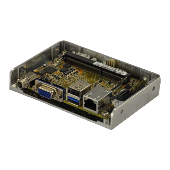
HYPER-BT 1.1 Introduction Figure 1-1: HYPER-BT The HYPER-BT PICO-ITX motherboard is an Intel® Atom™/Celeron® processor platform. It supports one 204-pin 1066/1333 MHz single-channel DDR3L SO-DIMM supports up to 8GB (J1900, N2930, E3845, E3827, E3826) or 4GB (N2807, E3825, E3815). The HYPER-BT includes a VGA connector and an iDP connector. Expansion and I/O include one USB 2.0 connector and one USB 3.0 connector on the rear panel, two USB 2.0 connectors by pin header and one SATA 3Gb/s connector. -
Page 13: Features
HYPER-BT 1.3 Features Some of the HYPER-BT motherboard features are listed below: PICO-ITX SBC supports Intel® 22nm Atom™ or Celeron® on-board SoC 12V only single voltage design for AT/ATX power by DC power jack VGA and iDP support for dual display 1.4 Connectors The connectors on the HYPER-BT are shown in the figure below. -
Page 14: Dimensions
HYPER-BT 1.5 Dimensions The dimensions of the board are listed below: Figure 1-3: Dimensions (mm) Page 4... -
Page 15: Data Flow
HYPER-BT 1.6 Data Flow Figure 1-4 shows the data flow between the system chipset, the CPU and other components installed on the motherboard. Figure 1-4: Data Flow Diagram Page 5... -
Page 16: Technical Specifications
HYPER-BT 1.7 Technical Specifications HYPER-BT technical specifications are listed below. Specification HYPER-BT Intel® Atom™ E3845 on-board SoC (1.91GHz, quad-core, 2MB cache, TDP=10W) Intel® Atom™ E3827 on-board SoC (1.75GHz, dual-core, 1MB cache, TDP=8W) Intel® Atom™ E3826 on-board SoC (1.46GHz, dual-core, 1MB cache, TDP=7W) Intel®... - Page 17 HYPER-BT Specification HYPER-BT Dual independent display Display Output 1 x VGA (up to 2560x1600@60Hz) 1 x iDP interface for HDMI, LVDS, VGA, DVI, DP (up to 3840x2160@60Hz) LAN: Intel® I211-AT PCIe controller Ethernet IT8587 Audio Realtek ALC888S HD codec supports 5.1 channel Software programmable support 1~255 sec.
-
Page 18: Table 1-2: Technical Specifications
HYPER-BT Specification HYPER-BT -30°C ~ 70°C Storage Temperature 5% ~ 95%, non-condensing Humidity Physical Specifications Dimensions 100 mm x 72 mm Weight GW/NW 600 g / 250 g Table 1-2: Technical Specifications Page 8... -
Page 19: Unpacking
HYPER-BT Chapter Unpacking Page 9... -
Page 20: Anti-Static Precautions
HYPER-BT 2.1 Anti-static Precautions WARNING! Static electricity can destroy certain electronics. Make sure to follow the ESD precautions to prevent damage to the product, and injury to the user. Make sure to adhere to the following guidelines: Wear an anti-static wristband: Wearing an anti-static wristband can prevent electrostatic discharge. -
Page 21: Packing List
HYPER-BT 2.3 Packing List NOTE: If any of the components listed in the checklist below are missing, do not proceed with the installation. Contact the IEI reseller or vendor the HYPER-BT was purchased from or contact an IEI sales representative directly by sending an email to sales@ieiworld.com. -
Page 22: Optional Items
HYPER-BT 2.4 Optional Items The following are optional components which may be separately purchased: Item and Part Number Image Dual-port USB cable without bracket, 210mm, p=2.0 (P/N: 32001-008600-200-RS) PS/2 keyboard and mouse Y cable without bracket, 140mm/120mm (P/N: 32006-000300-100-RS) RS-232 cable, 240mm, p=2.0 (P/N : 32200-000049-RS) DisplayPort to HDMI converter board (for IEI iDP connector) (P/N: DP-HDMI-R10) -
Page 23: Connectors
HYPER-BT Chapter Connectors Page 13... -
Page 24: Peripheral Interface Connectors
HYPER-BT 3.1 Peripheral Interface Connectors This chapter details all the jumpers and connectors. 3.1.1 HYPER-BT Layout The figures below show all the connectors and jumpers. Figure 3-1: Connector and Jumper Locations (Front) 3.1.2 Peripheral Interface Connectors The table below lists all the connectors on the board. Connector Type Label... -
Page 25: External Interface Panel Connectors
HYPER-BT Buzzer connector 2-pin wafer Clear CMOS button button J_CMOS1 CPU fan connector 4-pin wafer CPU_FAN1 DDR3L SO-DIMM slot DDR3L SO-DIMM slot DIMM1 Display port connector 20-pin header EC FW connector 2-pin wafer Front panel connector 6-pin wafer LAN LED connector 2-pin header Power button connector 2-pin wafer... -
Page 26: Internal Peripheral Connectors
HYPER-BT 3.2 Internal Peripheral Connectors The section describes all of the connectors on the HYPER-BT. 3.2.1 AT/ATX Mode Select Switch CN Label: J_ATX_AT1 CN Type: switch CN Location: See Figure 3-2 CN Settings: See Table 3-3 The AT/ATX mode select switch specifies the systems power mode as AT or ATX. AT/ATX mode select switch settings are shown in Table 3-3. -
Page 27: Audio Connector
HYPER-BT 3.2.2 Audio Connector CN Label: AUDIO1 CN Type: 10-pin header, p=2.00 mm CN Location: See Figure 3-3 CN Pinouts: See Table 3-4 The audio connector is connected to external audio devices including speakers and microphones for the input and output of audio signals to and from the system. Figure 3-3: Audio Connector Location Description Description... -
Page 28: Battery Connector
HYPER-BT 3.2.3 Battery Connector CAUTION: Risk of explosion if battery is replaced by an incorrect type. Only certified engineers should replace the on-board battery. Dispose of used batteries according to instructions and local regulations. CN Label: BAT1 CN Type: 2-pin wafer, p=1.25 mm CN Location: See Figure 3-4 CN Pinouts:... -
Page 29: Bios Fw Connector
HYPER-BT 3.2.4 BIOS FW Connector CN Label: JSPI1 6-pin wafer, p=1.25 mm CN Type: CN Location: See Figure 3-5 CN Pinouts: See Table 3-6 The BIOS FW connector is used for programming the BIOS. Figure 3-5: BIOS FW Connector Location Description Description +V1.8M_SPI_CON... -
Page 30: Buzzer Connector
HYPER-BT 3.2.5 Buzzer Connector CN Label: CN Type: 2-pin wafer, p=1.25 mm CN Location: See Figure 3-6 CN Pinouts: See Table 3-7 The buzzer connector is connected to the buzzer. NOTE: If you cannot find a good place to put a buzzer on the HYPER-BT, it is recommended to attach the buzzer onto the system chassis in which the HYPER-BT is installed. -
Page 31: Clear Cmos Button
HYPER-BT 3.2.6 Clear CMOS Button CN Label: J_CMOS1 button CN Type: CN Location: See Figure 3-7 CN Settings: See Table 3-8 If the HYPER-BT fails to boot due to improper BIOS settings, use the button to clear the CMOS data and reset the system BIOS information. The clear CMOS button settings are shown in Table 3-8. -
Page 32: Cpu Fan Connector
HYPER-BT 3.2.7 CPU Fan Connector CN Label: CPU_FAN1 4-pin wafer, p=2.54 mm CN Type: CN Location: See Figure 3-8 CN Pinouts: See Table 3-9 The fan connector attaches to a cooling fan. Figure 3-8: CPU Fan Connector Location Description Description +V12_FAN FANIO1_EC FANOUT1_EC... -
Page 33: Ddr3L So-Dimm Slot
HYPER-BT 3.2.8 DDR3L SO-DIMM Slot CN Label: DIMM1 DDR3L SO-DIMM slot CN Type: CN Location: See Figure 3-9 The DDR3L SO-DIMM slot is for DDR3L SO-DIMM memory module. Figure 3-9: DDR3L SO-DIMM Slot Location Page 23... -
Page 34: Display Port Connector
HYPER-BT 3.2.9 Display Port Connector CN Label: 20-pin box header, p=2.00 mm CN Type: CN Location: See Figure 3-10 CN Pinouts: See Table 3-10 The disport port connector provides flexible display function that supports VGA, DVI, LVDS, HDMI and DisplayPort via the disport port convert board. Figure 3-10: Display Port Connector Location Description Description... -
Page 35: Ec Fw Connector
HYPER-BT 3.2.10 EC FW Connector CN Label: 2-pin header, p=2.00 mm CN Type: CN Location: See Figure 3-11 CN Pinouts: See Table 3-11 The EC FW connector is used for programming the EC. Figure 3-11: EC FW Connector Location Description Description SMB_CLK_FW SMB_DATA_FW... -
Page 36: Front Panel Connector
HYPER-BT 3.2.11 Front Panel Connector CN Label: 6-pin wafer, p=2.00 mm CN Type: CN Location: See Figure 3-12 CN Pinouts: See Table 3-12 The front panel connector connects to the indicator LEDs on the system front panel. Figure 3-12: Front Panel Connector Location Description Description +V5S... -
Page 37: Lan Led Connector
HYPER-BT 3.2.12 LAN LED Connector CN Label: 2-pin header, p=2.00 mm CN Type: CN Location: See Figure 3-13 CN Pinouts: See Table 3-13 The LAN LED connectors connect to the LAN link LEDs on the system. Figure 3-13: LAN LED Connector Location Description Description L1_LINK_ACT-... -
Page 38: Power Button Connector
HYPER-BT 3.2.13 Power Button Connector CN Label: PWR_BTN1 2-pin wafer, p=2.00 mm CN Type: CN Location: See Figure 3-14 CN Pinouts: See Table 3-14 The power button connector is connected to a power switch on the system chassis to enable users to turn the system on and off. Figure 3-14: Power Button Connector Location Description PWRBTN_SW#... -
Page 39: Reset Button Connector
HYPER-BT 3.2.14 Reset Button Connector CN Label: RST_BTN1 2-pin wafer, p=2.00 mm CN Type: CN Location: See Figure 3-15 CN Pinouts: See Table 3-15 The reset button connector is connected to a reset switch on the system chassis to enable users to reboot the system when the system is turned on. -
Page 40: Rs-232 Serial Port Connector
HYPER-BT 3.2.15 RS-232 Serial Port Connector CN Label: COM1 10-pin header, p=2.00 mm CN Type: CN Location: See Figure 3-16 CN Pinouts: See Table 3-16 The serial connector provides RS-232 connection. Figure 3-16: RS-232 Serial Port Connector Location Description Description -NDCD1 -NDSR1 NSIN1... -
Page 41: Sata 3Gb/S Drive Connector
HYPER-BT 3.2.16 SATA 3Gb/s Drive Connector CN Label: SATA1 CN Type: 7-pin SATA connector CN Location: See Figure 3-17 The SATA 3Gb/s drive connector is connected to a SATA 3Gb/s drive. The SATA 3Gb/s drive transfers data at speeds as high as 3Gb/s. Figure 3-17: SATA 3Gb/s Drive Connector Location 3.2.17 SATA Power Connector CN Label:... -
Page 42: Usb Connector
HYPER-BT Figure 3-18: SATA Power Connector Location Description Table 3-17: SATA Power Connector Pinouts 3.2.18 USB Connector CN Label: USB_CAM1 CN Type: 8-pin header, p=2.00 mm CN Location: See Figure 3-19 CN Pinouts: See Table 3-18 The USB connector provides two USB 2.0 ports by dual-port USB cable. Figure 3-19: USB Connector Location Page 32... -
Page 43: External Peripheral Interface Connector Panel
HYPER-BT Description Description DATA2_N DATA3_P DATA2_P DATA3_N Table 3-18: USB Connector Pinouts 3.3 External Peripheral Interface Connector Panel Figure 3-20 shows the HYPER-BT external peripheral interface connector (EPIC) panel. The EPIC panel consists of the following: 1 x LAN connector ... -
Page 44: Power Connector
HYPER-BT Figure 3-21: LAN Connector Description Description MDIA3- MDIA2+ MDIA3+ MDIA1+ MDIA1- MDIA0- MDIA2- MDIA0+ Table 3-19: LAN Pinouts Description Description on: linked off: 10 Mb/s blinking: data is being sent/received green: 100 Mb/s orange: 1000 Mb/s Table 3-20: Connector LEDs 3.3.2 Power Connector CN Label: CN Type:... -
Page 45: Usb Connectors
HYPER-BT 3.3.3 USB Connectors CN Label: USB 2.0 & USB 3.0 ports CN Type: CN Location: See Figure 3-20 CN Pinouts: See Table 3-21 The HYPER-BT has one external USB 2.0 port and one external USB 3.0 port. The USB connector can be connected to a USB device. -
Page 46: Figure 3-22: Vga Connector
HYPER-BT Figure 3-22: VGA Connector Description Description Green Blue VGAVCC HOTPLUG DDCDAT HSYNC VSYNC DDCCLK Table 3-23: VGA Connector Pinouts Page 36... -
Page 47: Installation
HYPER-BT Chapter Installation Page 37... -
Page 48: Anti-Static Precautions
HYPER-BT 4.1 Anti-static Precautions WARNING: Failure to take ESD precautions during the installation of the HYPER-BT may result in permanent damage to the HYPER-BT and severe injury to the user. Electrostatic discharge (ESD) can cause serious damage to electronic components, including the HYPER-BT. - Page 49 HYPER-BT WARNING: The installation instructions described in this manual should be carefully followed in order to prevent damage to the HYPER-BT, HYPER-BT components and injury to the user. Before and during the installation please DO the following: Read the user manual: The user manual provides a complete description of the HYPER-BT installation instructions and configuration options.
-
Page 50: So-Dimm Installation
HYPER-BT 4.3 SO-DIMM Installation WARNING: Using incorrectly specified SO-DIMM may cause permanently damage the HYPER-BT. Please make sure the purchased SO-DIMM complies with the memory specifications of the HYPER-BT. SO-DIMM specifications compliant with the HYPER-BT are listed in the specification table of Chapter 1. To install an SO-DIMM, please follow the steps below and refer to Figure 4-1. -
Page 51: Internal Peripheral Device Connections
HYPER-BT 4.4 Internal Peripheral Device Connections This section outlines the installation of peripheral devices to the on-board connectors 4.4.1 Audio Kit Installation The Audio Kit that came with the HYPER-BT connects to the audio connector on the HYPER-BT. The audio kit consists of three audio jacks. Mic-in connects to a microphone. Line-in provides a stereo line-level input to connect to the output of an audio device. -
Page 52: Sata Drive Connection
HYPER-BT Step 3: Connect the audio devices. Connect speakers to the line-out audio jack. Connect the output of an audio device to the line-in audio jack. Connect a microphone to the mic-in audio jack.Step 0: 4.4.2 SATA Drive Connection The HYPER-BT is shipped with a SATA drive cable. To connect the SATA drive to the connector, please follow the steps below. -
Page 53: Single Rs-232 Cable
HYPER-BT Step 4: To remove the SATA cable from the SATA connector, press the clip on the connector at the end of the cable. Step 0: 4.4.3 Single RS-232 Cable The single RS-232 cable consists of one serial port connector attached to a serial communications cable that is then attached to a D-sub 9 male connector. -
Page 54: Available Drivers
HYPER-BT 4.5 Available Drivers All the drivers for the HYPER-BT are available on IEI Resource Download Center (https://download.ieiworld.com). Type HYPER-BT and press Enter to find all the relevant software, utilities, and documentation. Figure 4-5: IEI Resource Download Center 4.5.1 Driver Download To download drivers from IEI Resource Download Center, follow the steps below. - Page 55 HYPER-BT Step 7: Click the driver file name on the page and you will be prompted with the following window. You can download the entire ISO file ( ), or double click an individual item to find its driver file and click the file name to download ( NOTE: To install software from the downloaded ISO image file in Windows 8, 8.1 or 10, double-click the ISO file to mount it as a virtual drive to view...
-
Page 56: Bios
HYPER-BT Chapter BIOS Page 46... -
Page 57: Introduction
HYPER-BT 5.1 Introduction The BIOS is programmed onto the BIOS chip. The BIOS setup program allows changes to certain system settings. This chapter outlines the options that can be changed. NOTE: Some of the BIOS options may vary throughout the life cycle of the product and are subject to change without prior notice. -
Page 58: Getting Help
HYPER-BT Function Decrease the numeric value or make changes F1 key General help, only for Status Page Setup Menu and Option Page Setup Menu F2 key Load previous values. F3 key Load optimized defaults F4 key Save changes and Exit BIOS Esc key Main Menu –... -
Page 59: Main
HYPER-BT The following sections completely describe the configuration options found in the menu items at the top of the BIOS screen and listed above. 5.2 Main The Main BIOS menu (BIOS Menu 1) appears when the BIOS Setup program is entered. The Main menu gives an overview of the basic system information. -
Page 60: Advanced
HYPER-BT The System Overview field also has two user configurable fields: System Date [xx/xx/xx] Use the System Date option to set the system date. Manually enter the day, month and year. System Time [xx:xx:xx] Use the System Time option to set the system time. Manually enter the hours, minutes and seconds. -
Page 61: Acpi Settings
HYPER-BT 5.3.1 ACPI Settings The ACPI Settings menu (BIOS Menu 3) configures the Advanced Configuration and Power Interface (ACPI) options. Aptio Setup Utility – Copyright (C) 2013 American Megatrends, Inc. Advanced ACPI Settings ACPI Sleep State [S3 (Suspend to RAM] ---------------------- : Select Screen ↑... -
Page 62: It8528 Super Io Configuration
HYPER-BT 5.3.2 IT8528 Super IO Configuration Use the IT8528 Super IO Configuration menu (BIOS Menu 4) to set or change the configurations for the serial ports. Aptio Setup Utility – Copyright (C) 2013 American Megatrends, Inc. Advanced IT8528 Super IO Configuration Set Parameters of Serial Port 1 (COMA) Super IO Chip... -
Page 63: Hardware Monitor
HYPER-BT Serial Port [Enabled] Use the Serial Port option to enable or disable the serial port. Disable the serial port Disabled Enable the serial port Enabled EFAULT Change Settings [Auto] Use the Change Settings option to change the serial port IO port address and interrupt address. -
Page 64: Smart Fan Mode Configuration
HYPER-BT Aptio Setup Utility – Copyright (C) 2013 American Megatrends, Inc. Advanced PC Health Status Enable or Disable Smart > Smart Fan Function CPU temperature :+42 C CPU Fan Speed :N/A SOC_VCC :+0.774 V V1.0S :+0.996 V V1.35S :+1.348 V V1.35_DDR3 :+1.324 V ---------------------... -
Page 65: Bios Menu 7: Smart Fan Mode Configuration
HYPER-BT Aptio Setup Utility – Copyright (C) 2013 American Megatrends, Inc. Advanced Smart Fan Mode Configuration CPU Smart Fan control settings. CPU Smart Fan control [Auto PWM Mode] Temperature of Off Temperature of Start Start PWM --------------------- : Select Screen Slope(Duty Cycle) ↑... - Page 66 HYPER-BT the CPU is at a very high temperature and therefore cause the system to be damaged. The Temperature of Off option can only be set if the CPU Smart Fan control option is set to Auto Mode. If the CPU temperature is lower than Temperature of Off, the fan speed change to be lowest.
-
Page 67: Rtc Wake Settings
HYPER-BT Minimum Value: 0 Maximum Value: 100 Slope (Duty Cycle) [4] The Slope (Duty Cycle) option can only be set if the CPU Smart Fan control option is set to Auto Mode. Use the Slope (Duty Cycle) option to select the linear rate at which the PWM mode increases with respect to an increase in temperature. -
Page 68: Serial Port Console Redirection
HYPER-BT Wake system with Fixed Time [Disabled] Use the Wake system with Fixed Time option to enable or disable the system wake on alarm event. Disabled The real time clock (RTC) cannot generate a wake EFAULT event Enabled If selected, the Wake up every day option appears allowing you to enable to disable the system to wake... -
Page 69: Console Redirection Settings
HYPER-BT Aptio Setup Utility – Copyright (C) 2013 American Megatrends, Inc. Advanced COM1 Console Redirection Console Redirection [Disabled] Enable or Disable > Console Redirection Settings --------------------- : Select Screen ↑ ↓: Select Item Enter Select General Help Previous Values Optimized Defaults Save Exit... -
Page 70: Bios Menu 10: Console Redirection Settings
HYPER-BT Aptio Setup Utility – Copyright (C) 2013 American Megatrends, Inc. Advanced COM1 Emulation: ANSI: Console Redirection Settings Extended ASCII char set. VT100: ASCII char set. Terminal Type [ANSI] VT100+: Extends VT100 to Bits per second [115200] support color, function Data Bits keys, etc. - Page 71 HYPER-BT 38400 Sets the serial port transmission speed at 38400. Sets the serial port transmission speed at 57600. 57600 115200 Sets the serial port transmission speed at 115200. EFAULT Data Bits [8] Use the Data Bits option to specify the number of data bits. ...
-
Page 72: Cpu Configuration
HYPER-BT 5.3.6 CPU Configuration Use the CPU Configuration menu (BIOS Menu 5) to view detailed CPU specifications and configure the CPU. Aptio Setup Utility – Copyright (C) 2013 American Megatrends, Inc. Advanced CPU Configuration When enabled, a VMM can utilize the additional Intel(R) Celeron(R) CPU N2807 @ 1.58GHz hardware capabilities CPU Signature... -
Page 73: Ide Configuration
HYPER-BT Disabled Disables the Intel Speed Step Technology. Enables the Intel Speed Step Technology. Enabled EFAULT 5.3.7 IDE Configuration Use the IDE Configuration menu (BIOS Menu 12) to change and/or set the configuration of the SATA devices installed in the system. Aptio Setup Utility –... -
Page 74: Usb Configuration
HYPER-BT SATA Port 0 HotPlug [Disabled] Use the Serial-ATA Port 0 HotPlug option to enable or disable the SATA device hot plug. Disables the SATA device hot plug. Disabled Enables the SATA device hot plug Enabled EFAULT 5.3.8 USB Configuration Use the USB Configuration menu (BIOS Menu 13) to read USB configuration information and configure the USB settings. -
Page 75: Chipset
HYPER-BT does not become available until a USB compatible operating system is fully booted with all USB drivers loaded. When this option is enabled, any attached USB mouse or USB keyboard can control the system even when there is no USB driver loaded onto the system. -
Page 76: North Bridge Configuration
HYPER-BT 5.4.1 North Bridge Configuration Use the North Bridge Configuration menu (BIOS Menu 15) to configure the Intel IGD settings. Aptio Setup Utility – Copyright (C) 2013 American Megatrends, Inc. Chipset > Intel IGD Configuration Configure Intel IGD Settings. Memory Information Total Memory 4096 MB(LPDDR3) Memory Slot0... -
Page 77: Bios Menu 16: Integrated Graphics
HYPER-BT Aptio Setup Utility – Copyright (C) 2013 American Megatrends, Inc. Chipset DVMT Pre-Allocated [256M] Select DVMT 5.0 DVMT Total Gfx Mem [MAX] Pre-Allocated (Fixed) Graphics Memory size Primary IGFX Boot Display [VBIOS Default] used by the Internal Graphics Device. --------------------- : Select Screen ↑... -
Page 78: Southbridge Configuration
HYPER-BT Primary IGFX Boot Display [VBIOS Default] Use the Primary IGFX Boot Display option to select the display device used by the system when it boots. For dual display support, select “VBIOS Deafult.” Configuration options are listed below. VBIOS Default D EFAULT ... -
Page 79: Security
HYPER-BT Audio Controller [Enabled] Use the Audio Controller option to enable or disable the High Definition Audio controller. The onboard High Definition Audio controller is disabled Disabled The onboard High Definition Audio controller is detected Enabled EFAULT automatically and enabled 5.5 Security Use the Security menu (BIOS Menu 18) to set system and user passwords. -
Page 80: Boot
HYPER-BT 5.6 Boot Use the Boot menu (BIOS Menu 17) to configure system boot options. Aptio Setup Utility – Copyright (C) 2013 American Megatrends, Inc. Main Advanced Chipset Security Boot Save & Exit Boot Configuration Select the keyboard Bootup NumLock State [On] NumLock state Quiet Boot... - Page 81 HYPER-BT Quiet Boot [Enabled] Use the Quiet Boot BIOS option to select the screen display when the system boots. Normal POST messages displayed Disabled OEM Logo displayed instead of POST messages Enabled EFAULT Option ROM Messages [Force BIOS] Use the Option ROM Messages option to set the Option ROM display mode.
-
Page 82: Exit
HYPER-BT Boot Option Priority Use the Boot Option Priority function to set the system boot sequence from the available devices. The drive sequence also depends on the boot sequence in the individual device section. 5.7 Exit Use the Exit menu (BIOS Menu 20) to load default BIOS values, optimal failsafe values and to save configuration changes. - Page 83 HYPER-BT Restore Defaults Use the Restore Defaults option to load the optimal default values for each of the parameters on the Setup menus. F3 key can be used for this operation. Save as User Defaults Use the Save as User Defaults option to save the changes done so far as user defaults. ...
-
Page 84: A Regulatory Compliance
HYPER-BT Appendix Regulatory Compliance Page 74... - Page 85 HYPER-BT DECLARATION OF CONFORMITY This equipment has been tested and found to comply with specifications for CE marking. If the user modifies and/or installs other devices in the equipment, the CE conformity declaration may no longer apply. FCC WARNING This equipment complies with Part 15 of the FCC Rules. Operation is subject to the following two conditions: ...
-
Page 86: B Product Disposal
HYPER-BT Appendix Product Disposal Page 76... - Page 87 HYPER-BT CAUTION: Risk of explosion if battery is replaced by an incorrect type. Only certified engineers should replace the on-board battery. Dispose of used batteries according to instructions and local regulations. Outside the European Union–If you wish to dispose of used electrical and electronic products outside the European Union, please contact your local authority so as to comply with the correct disposal method.
-
Page 88: Cbios Menu Options
HYPER-BT Appendix BIOS Menu Options Page 78... - Page 89 HYPER-BT System Date [xx/xx/xx] ......................50 System Time [xx:xx:xx] ....................... 50 ACPI Sleep State [S3 only (Suspend to RAM)] ..............51 Serial Port [Enabled] ......................53 Change Settings [Auto] ....................... 53 PC Health Status ........................54 CPU Smart Fan control [Auto PWM Mode] ................ 55 Temperature of Off [75] .......................
- Page 90 HYPER-BT Quiet Boot [Enabled] ......................71 Option ROM Messages [Force BIOS] ................. 71 UEFI Boot [Disabled] ......................71 Launch PXE OpROM [Disabled] ..................71 Boot Option Priority ......................72 Save Changes and Reset ....................72 Discard Changes and Reset ....................72 Restore Defaults ........................
-
Page 91: D Error Beep Code
HYPER-BT Appendix Error Beep Code Page 81... -
Page 92: Pei Beep Codes
HYPER-BT D.1 PEI Beep Codes Number of Beeps Description Memory not Installed Memory was installed twice (InstallPeiMemory routine in PEI Core called twice) Recovery started DXEIPL was not found DXE Core Firmware Volume was not found Recovery failed S3 Resume failed Reset PPI is not available D.2 DXE Beep Codes Number of Beeps... -
Page 93: E Hazardous Materials Disclosure
HYPER-BT Appendix Hazardous Materials Disclosure Page 83... -
Page 94: Rohs Ii Directive (2015/863/Eu)
HYPER-BT E.1 RoHS II Directive (2015/863/EU) The details provided in this appendix are to ensure that the product is compliant with the RoHS II Directive (2015/863/EU). The table below acknowledges the presences of small quantities of certain substances in the product, and is applicable to RoHS II Directive (2015/863/EU). -
Page 95: China Rohs
HYPER-BT E.2 China RoHS 此附件旨在确保本产品符合中国 RoHS 标准。以下表格标示此产品中某有毒物质的含量符 合中国 RoHS 标准规定的限量要求。 本产品上会附有”环境友好使用期限”的标签,此期限是估算这些物质”不会有泄漏或突变”的 年限。本产品可能包含有较短的环境友好使用期限的可替换元件,像是电池或灯管,这些 元件将会单独标示出来。 部件名称 有毒有害物质或元素 壳体 显示 印刷电路板 金属螺帽 电缆组装 风扇组装 电力供应组装 电池 O: 表示该有毒有害物质在该部件所有物质材料中的含量均在 SJ/T11364-2014 與 GB/T26572-2011 标准规定的限量要求以下。 X: 表示该有毒有害物质至少在该部件的某一均质材料中的含量超出 SJ/T11364-2014 與 GB/T26572-2011 标准规定的限量要求。 Page 85...
Need help?
Do you have a question about the HYPER-BT-E38 1 Series and is the answer not in the manual?
Questions and answers