Table of Contents
Advertisement
MODEL G0715P
POLAR BEAR SERIES
®
10" HYBRID TABLE SAW
w/RIVING KNIFE
OWNER'S MANUAL
232857
COPYRIGHT © JULY, 2010 BY GRIZZLY INDUSTRIAL, INC. REVISED JANUARY, 2016 (MN)
WARNING: NO PORTION OF THIS MANUAL MAY BE REPRODUCED IN ANY SHAPE
OR FORM WITHOUT THE WRITTEN APPROVAL OF GRIZZLY INDUSTRIAL, INC.
(FOR MODELS MANUFACTURED SINCE 4/11) #13072TRCRBLTSJB PRINTED IN CHINA
Advertisement
Table of Contents

Subscribe to Our Youtube Channel
Related Manuals for Grizzly G0715P


Summary of Contents for Grizzly G0715P
- Page 1 KNIFE OWNER'S MANUAL 232857 COPYRIGHT © JULY, 2010 BY GRIZZLY INDUSTRIAL, INC. REVISED JANUARY, 2016 (MN) WARNING: NO PORTION OF THIS MANUAL MAY BE REPRODUCED IN ANY SHAPE OR FORM WITHOUT THE WRITTEN APPROVAL OF GRIZZLY INDUSTRIAL, INC. (FOR MODELS MANUFACTURED SINCE 4/11) #13072TRCRBLTSJB PRINTED IN CHINA...
- Page 2 This manual provides critical safety instructions on the proper setup, operation, maintenance, and service of this machine/tool. Save this document, refer to it often, and use it to instruct other operators. Failure to read, understand and follow the instructions in this manual may result in fire or serious personal injury—including amputation, electrocution, or death.
-
Page 3: Table Of Contents
Machine Description ........2 Push Sticks ..........49 Identification ........... 3 Push Blocks ..........50 G0715P Machine Data Sheet ......4 Narrow-Rip Auxiliary Fence & Push Block .. 51 Outfeed & Support Tables ......53 SECTION 1: SAFETY ........7 Crosscut Sled.......... -
Page 4: Introduction
For your convenience, we post all available man- ciently transfers power. uals and manual updates for free on our website at www.grizzly.com. Any updates to your model Includes a camlock T-shaped fence with HDPE of machine will be reflected in these documents face, miter gauge, quick-release spreader/blade as soon as they are complete. -
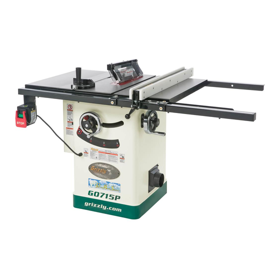
Page 5: Identification
Blade Handle Tilt 4" Dust Port Scale Figure 1. Model G0715P Identification of main controls and components. For Your Own Safety Read Instruction Manual Before Operating Saw a) Wear eye protection. b) Use saw-blade guard and spreader for every operation for which it can be used, including all through sawing. -
Page 6: G0715P Machine Data Sheet
MACHINE DATA SHEET Customer Service #: (570) 546-9663 · To Order Call: (800) 523-4777 · Fax #: (800) 438-5901 MODEL G0715P 10" HYBRID TABLE SAW WITH RIVING KNIFE, POLAR BEAR SERIES Product Dimensions: Weight................................393 lbs. Width (side-to-side) x Depth (front-to-back) x Height................60 x 36 x 40 in. - Page 7 The information contained herein is deemed accurate as of 1/28/2016 and represents our most recent product specifications. Model G0715P PAGE 2 OF 3 Due to our ongoing improvement efforts, this information may not accurately describe items previously purchased. Model G0715P (Mfg. 4/11+)
- Page 8 The information contained herein is deemed accurate as of 1/28/2016 and represents our most recent product specifications. Model G0715P PAGE 3 OF 3 Due to our ongoing improvement efforts, this information may not accurately describe items previously purchased. Model G0715P (Mfg. 4/11+)
-
Page 9: Section 1: Safety
Everyday ery. Never operate under the influence of drugs or eyeglasses are not approved safety glasses. alcohol, when tired, or when distracted. Model G0715P (Mfg. 4/11+) - Page 10 INTENdEd usAGE. Only use machine for its machine in good working condition. A machine intendedpurposeandnevermakemodifications that is improperly maintained could malfunction, not approved by Grizzly. Modifying machine or leadingtoseriouspersonalinjuryordeath. using it differently than intended may result in ChECK dAMAGEd PARTs. Regularly inspect...
-
Page 11: Additional Safety For Table Saws
Cutting metal, operation “freehand” (making a cut without using a glass, stone, tile, etc. increases the risk of operator fence, miter gauge, or other guide). injury due to kickback or flying particles. Model G0715P (Mfg. 4/11+) -
Page 12: Preventing Kickback
Making a deep often the case that the operator’s hands are non-through cut will greatly increase the pulled into the blade during kickback. chance of kickback. -10- Model G0715P (Mfg. 4/11+) -
Page 13: Glossary Of Terms
The following is a list of common definitions, terms and phrases used throughout this manual as they relate to this table saw and woodworking in general. Become familiar with these terms for assembling, adjusting or operating this machine. Your safety is VERY important to us at Grizzly! Arbor: A metal shaft extending from the drive... -
Page 14: Section 2: Power Supply
Nominal Voltage ....... 110V/120V meets the requirements in the following section. Cycle ............60 Hz Phase ........... Single-Phase Circuit Rating ........20 Amps Plug/Receptacle ......NEMA 5-20 -12- Model G0715P (Mfg. 4/11+) -
Page 15: Grounding Requirements
5-20 RECEPTACLE and receptacle, and meet the following require- ments: Neutral Minimum Gauge Size ......12 AWG Maximum Length (Shorter is Better)..50 ft. 5-20 PLUG Grounding Prong Figure 3. Typical 5-20 plug and receptacle. -13- Model G0715P (Mfg. 4/11+) -
Page 16: Voltage Conversion
Figure 5, then tighten the four screws loos- ened in Step 2. This section shows how to convert the Model G0715P from 220V to 110V. The plug needed for SWITCH this conversion can be purchased at any local Motor Rewired... -
Page 17: Section 3: Setup
Otherwise, filing a freight claim can be difficult. When you are completely satisfied with the condi- tion of your shipment, inventory the contents. SUFFOCATION HAZARD! Keep children and pets away from plastic bags or packing materials shipped with this machine. Discard immediately. -15- Model G0715P (Mfg. 4/11+) -
Page 18: Hardware Recognition Chart
Hardware Recognition Chart -16- Model G0715P (Mfg. 4/11+) -
Page 19: Inventory
Inventory The following is a description of the main compo- nents shipped with each Model G0715P. Lay the components out to inventory them. Note: If you can't find an item on this list, check the mounting location on the machine or examine the packaging materials carefully. - Page 20 Cap Screws M8-1.25 x 35 (Rear Rail/Wing) ..2 Hex Nuts M8-1.25 (Rear Rail/Wing) ....2 Flat Washers 8mm (Rear Rail/Wing) ....2 Lock Washers 8mm (Rear Rail/Wing) ....2 Figure 10. Inventory needed to install the fence on the Model G0715P. -18- Model G0715P (Mfg. 4/11+)
-
Page 21: Cleanup
Repeat Steps 2–3 as necessary until clean, then coat all unpainted surfaces with a quality metal protectant to prevent rust. -19- Model G0715P (Mfg. 4/11+) -
Page 22: Site Considerations
Shadows, glare, or strobe effects that may distract access restricted location. or impede the operator must be eliminated. = Power Connection " 4" Dust Port Access Door Swing at 90º 39" Min. 30" Figure 11. Minimum working clearances. -20- Model G0715P (Mfg. 4/11+) -
Page 23: Assembly
Figure 15. Extension wings installed. the appropriate metal protectant (refer to Lubrication on Page 58 for the location of gears). -21- Model G0715P (Mfg. 4/11+) - Page 24 11. While standing at the front of the table, pull the rail tube toward you as far as possible, then final tighten the fasteners installed in Step 10. This will help make sure there is enough room for the fence to slide. -22- Model G0715P (Mfg. 4/11+)
- Page 25 Miter Slot to Blade Parallelism on Page 63. Note: Make sure the cam foot contacts the cam on the fence lock handle before you place the fence on the rail; otherwise, the fence will not lock onto the rail tube. -23- Model G0715P (Mfg. 4/11+)
-
Page 26: Power Connection
22. Install the blade guard as outlined on Page instructions in this manual have been com- pleted. Clear away all tools and objects used during setup from the machine. Insert the plug into a matching receptacle. -24- Model G0715P (Mfg. 4/11+) -
Page 27: Dust Collection
Figure 25, and tightly secure it in place with a hose clamp. Tug the hose to make sure it does not come DO NOT operate the Model G0715P without off. Note: A tight fit is necessary for proper an adequate dust collection system. This performance. -
Page 28: Test Run
Insert the switch disabling pin through the Adjustments that should be verified: green START button, as shown in Figure Blade Tilt Stop Accuracy (Page 61). Miter Slot Parallel to Blade (Page 63). Spreader/Riving Knife Alignment (Page 66). -26- Model G0715P (Mfg. 4/11+) -
Page 29: Section 4: Operations
Regardless of the content in this section, Grizzly Industrial will not be held liable for Stops the machine immediately after the cut accidents caused by lack of training. -
Page 30: Basic Controls
Fence Lock: After adjusting the fence to the desired width of cut, lock it in place by firmly push- Figure 30. Example of a through cut (blade ing the fence lock down until it stops. guard not shown for illustrative clarity). -28- Model G0715P (Mfg. 4/11+) -
Page 31: Workpiece Inspection
Excessive Warping: Workpieces with exces- sive cupping, bowing, or twisting are danger- ous to cut because they are unstable and may move unpredictably when being cut. • Minor Warping: Slightly cupped workpieces Figure 31. Ripping blade. can be safely supported with cupped side facing the table or fence; however, work- pieces supported on the bowed side will rock during the cut, which could cause kickback. -29- Model G0715P (Mfg. 4/11+) - Page 32 The blade angle is adjustable on the hub, and the width of the dado cut is controlled by the angle setting of the blade. Flat Figure 33. Combination blade. Figure 35. Stacked dado blade. -30- Model G0715P (Mfg. 4/11+)
-
Page 33: Blade Installation
DO NOT over- tighten. Arbor Lock Figure 36. Location of arbor lock. Note: The arbor nut has right hand threads; turn it counterclockwise to loosen. -31- Model G0715P (Mfg. 4/11+) -
Page 34: Blade Guard Assembly
The spreader also acts as a barrier behind the blade to shield hands from being pulled into the blade if a kickback occurs. -32- Model G0715P (Mfg. 4/11+) - Page 35 Figure 41, and will be parallel with the to be fixed/replaced. blade. Alignment Zone Spreader or Riving Knife Straightedge Blade Figure 41. Spreader/riving knife alignment zone. -33- Model G0715P (Mfg. 4/11+)
- Page 36 Use good judgment! hooks, as shown in Figure 43. Arresting Hooks (One Shown) Pawl Figure 43. Pawl disabled. -34- Model G0715P (Mfg. 4/11+)
-
Page 37: Riving Knife
Top Distance Minimum 3mm Maximum 8mm Bottom Distance Minimum 3mm Maximum 8mm Figure 45. Allowable top and bottom distances between riving knife and blade. -35- Model G0715P (Mfg. 4/11+) -
Page 38: Ripping
Failure to do this could devices. result in serious personal injury or death. Plug the saw into the power source, turn it ON, and allow it to reach full speed. -36- Model G0715P (Mfg. 4/11+) -
Page 39: Crosscutting
Crosscutting instruc- Turn OFF the saw and allow the blade to tions. come to a complete stop before removing the cut-off piece. Failure to follow this warn- ing could result in serious personal injury -37- Model G0715P (Mfg. 4/11+) -
Page 40: Blade Tilt/Bevel Cuts
Figure 50. Example of a dado being cut with a dado blade. DO NOT make through cuts with a dado blade. Dado blades are only intended for non-through cuts. Failure to heed this warning could result in serious injury. -38- Model G0715P (Mfg. 4/11+) - Page 41 Dado Blade Cut 1 Fence Workpiece Cut 2 Fence Workpiece Cut 3 Fence Workpiece Finished Dado Cut Fence Workpiece Figure 51. Example of dado being cut with multiple light cuts, instead of one deep cut. -39- Model G0715P (Mfg. 4/11+)
- Page 42 Align the blade to cut one of the dado sides, as shown in Figure 52. Cuts 3+ Fence Workpiece Blade Cut 1 Fence Workpiece Figure 54. Additional single blade dado cuts. Figure 52. First cut for a single-blade dado. -40- Model G0715P (Mfg. 4/11+)
-
Page 43: Rabbet Cutting
ALWAYS replace the blade guard after dadoing is complete. -41- Model G0715P (Mfg. 4/11+) - Page 44 — If the workpiece is very tall, or is unstable Figure 58. Second cut to create a rabbet. when placed against the fence, lay it flat on the table and use a dado blade to perform the rabbet cut. -42- Model G0715P (Mfg. 4/11+)
-
Page 45: Resawing
⁄ ". #8 x 2" ⁄ " Wood Screw ⁄ " Assembled Resaw Barrier Figure 59. Resaw barrier. -43- Model G0715P (Mfg. 4/11+) -
Page 46: Auxiliary Fence
Auxiliary Facing the workpiece, as shown in Figure 61. Now Fence clamp the resaw barrier to the top of the table saw at both ends. Figure 60. Auxiliary fence. -44- Model G0715P (Mfg. 4/11+) - Page 47 Flip the workpiece end for end, keeping the same side against the fence, and run the workpiece through the blade. -45- Model G0715P (Mfg. 4/11+)
-
Page 48: Section 5: Shop Made Safety Accessories
Step 3 will bend without breaking. NOTICE Cut a 30º angle at one end of the board. Only Steps 1–3 are required to make a clamp-mounted featherboard. Refer to Page 48 for instructions on clamping. -46- Model G0715P (Mfg. 4/11+) - Page 49 Figure 65. Miter bar pattern. Now, proceed to Mounting Featherboard in Miter Slot on Page 48. Drill a ⁄ " hole in the center of the bar, then countersink the bottom to fit a ⁄ "-20 flat head screw. -47- Model G0715P (Mfg. 4/11+)
- Page 50 Note: The featherboard should be placed firmly enough against the workpiece to keep it against the fence but not so tight that it is difficult to feed the workpiece. -48- Model G0715P (Mfg. 4/11+)
-
Page 51: Push Sticks
⁄ " Grid from the blade! Figure 71. Template for a basic shop-made push stick (not shown at actual size). -49- Model G0715P (Mfg. 4/11+) -
Page 52: Push Blocks
Lip for pushing workpiece ⁄ " Grid 9"−10" Minimum Length Figure 74. Template for a shop-made push block (shown at 50% of full size). -50- Model G0715P (Mfg. 4/11+) -
Page 53: Narrow-Rip Auxiliary Fence & Push Block
Attach the handle to the base with #8 x 1 ⁄ " Length of Table wood screws, and attach the lip to the base Saw Rip Fence with cyanoacrylate type wood glue. ⁄ " Figure 75. Auxiliary fence dimensions. -51- Model G0715P (Mfg. 4/11+) - Page 54 Turn OFF the saw and allow the blade to fence. come to a complete stop before removing the cut-off piece. Failure to follow this warn- ing could result in serious personal injury. -52- Model G0715P (Mfg. 4/11+)
-
Page 55: Outfeed & Support Tables
Crosscut Sled Support Outfeed Table Table Figure 82. Example of crosscut sled. Figure 81. Example of outfeed & support tables. -53- Model G0715P (Mfg. 4/11+) -
Page 56: Section 6: Aftermarket Accessories From Grizzly
Figure 84. G1163 1HP dust collector. G7314Z—Heavy-Duty SHOP FOX Mobile Base ® Make your Model G0715P mobile with this popular T20392—Success with Tablesaws patented mobile base. The unique outrigger type The tablesaw is the cornerstone of any work- supports increase stability and lower machine shop, yet, too many woodworkers still haven’t... - Page 57 No staggered steps or round bottoms like a wobble-dado leaves! Cuts in all directions - rip, cross-cut, miter, any depth. Cuts all sized grooves ⁄ " through ⁄ " increments. Figure 89. H4756 Dado Head. -55- Model G0715P (Mfg. 4/11+)
- Page 58 T-9 4 oz Spray ® H3788—G96 Gun Treatment 12 oz Spray ® Figure 93. H3309 SHOP FOX Featherboard. ® H3789—G96 Gun Treatment 4.5 oz Spray ® Figure 91. Recommended products for protecting your cast iron table top. -56- Model G0715P (Mfg. 4/11+)
-
Page 59: Section 7: Maintenance
OxiSolv Blade & Bit ® Cleaner. Monthly • Check V-belt tension, damage, or wear (Page 71). Every 6–12 Months Lubricate the trunnions (Page 58). • • Lubricate the elevation and tilt leadscrews (Page 58). -57- Model G0715P (Mfg. 4/11+) -
Page 60: Lubrication
Move the blade tilt back- and-forth to spread the grease (see Figure 94). Figure 96. Leadscrew. Front Trunnion Slide Figure 94. Trunnion slide (only front slide shown). -58- Model G0715P (Mfg. 4/11+) -
Page 61: Section 8: Service
8. Motor fan rubbing on fan cover. 8. Fix/replace fan cover; replace loose/damaged fan. 9. Arbor bearings at fault. 9. Replace arbor housing bearings; replace arbor. 10. Motor bearings at fault. 10. Test by rotating shaft; grinding/loose shaft requires bearing replacement. -59- Model G0715P (Mfg. 4/11+) - Page 62 2. Blade is warped. through table saw. 3. Fence is not parallel to blade. 3. Make fence parallel to blade (Page 68). 4. Make table parallel to blade (Page 63). 4. Table top is not parallel to blade. -60- Model G0715P (Mfg. 4/11+)
-
Page 63: Blade Tilt Stops
Without turning the blade tilt leadscrew, fin- gers, then tightening the screw. ger-tighten the 90° collar against the trunnion bracket, then tighten the two cap screws to secure the collar position. -61- Model G0715P (Mfg. 4/11+) - Page 64 —If the blade is not 45° to the table, you will need to adjust the 45° stop collar. Proceed to the next step. Tilt the blade to 35°, so there is room for the stop collar to move. -62- Model G0715P (Mfg. 4/11+)
-
Page 65: Miter Slot To Blade Parallelism
— If the blade tip does not touch the end of the adjustable square similar to the first Blade tilted to 90º measurement, the table will need to be adjusted. Proceed to Step 6. Front Figure 102. Example of adjusting blade to miter slot. -63- Model G0715P (Mfg. 4/11+) - Page 66 Skip ahead to Step 15. —If the blade was parallel with the miter slot at 90° but not at 45°, continue to Step 12. Rear Trunnion Mounting Cap Screw (1 of 2) Figure 105. Rear trunnion mount cap screw. -64- Model G0715P (Mfg. 4/11+)
- Page 67 — If the distance of B is greater than A, remove one shim from each side of the rear trunnion (#3 and #4 on Figure 108). Rear Trunnion Figure 108. Shim removal procedure diagram B. -65- Model G0715P (Mfg. 4/11+)
-
Page 68: Spreader Or Riving Knife Alignment
Possible Tools Needed Hex Wrench 5mm ..........1 Bottom Alignment To adjust the spreader/riving knife position: DISCONNECT SAW FROM POWER! Figure 109. Checking top and bottom riving knife parallelism with blade. Remove the table insert. -66- Model G0715P (Mfg. 4/11+) -
Page 69: Fence Adjustments
— If this does not work, remove it to straight- fence parallelism and clamping pressure. Back out the rear set screws until they are — If you cannot straighten it properly, replace just threaded into the fence flange (see Figure 112). -67- Model G0715P (Mfg. 4/11+) - Page 70 Step 9. Fence Flush Face Miter Side View (Good) 90° Square Slots Fence Table Overlap Side View (Bad) Figure 114. Checking if fence is square to table. Top View Figure 115. Aligning fence to miter slot. -68- Model G0715P (Mfg. 4/11+)
- Page 71 " between the marked tooth and the fence face. Re-install the fence and measure the dis- tance again between the marked tooth and the fence face. The rear measurement should " greater than previously measured in Step 4. -69- Model G0715P (Mfg. 4/11+)
-
Page 72: Miter Gauge Adjustments
90°, except using a 45° and 30° square or adjustable square to verify that the miter body is 45° to the blade, as shown in. Miter Gauge Figure 117. Checking 90° stop on miter gauge. -70- Model G0715P (Mfg. 4/11+) -
Page 73: Belt Tension & Replacement
V-belt tension. sion. The belt is correctly tensioned when there is approximately ⁄ " deflection when it Close the motor access cover. is pushed with moderate pressure, as shown in Figure 120. -71- Model G0715P (Mfg. 4/11+) -
Page 74: Section 9: Wiring
Technical source. Support at (570) 546-9663. The photos and diagrams included in this section are best viewed in color. You can view these pages in color at www.grizzly.com. -72- Model G0715P (Mfg. 4/11+) -
Page 75: Wiring Diagram
Rewired for 110V (See Figure 121) Start Capacitor Capacitor 200MFD 60MFD 250VAC 300VAC 110V/220V MOTOR (See Figure 122) Motor Rewired Motor Prewired for 110V for 220V Ground Ground Rewired for 110V READ ELECTRICAL SAFETY -73- Model G0715P (Mfg. 4/11+) ON PAGE 72! -
Page 76: Electrical Components
Electrical Components ON/OFF Circuit Capacitors Switch Breaker Figure 121. Motor capacitors. Figure 123. Switch box components. Motor Junction Figure 122. Motor junction box. READ ELECTRICAL SAFETY -74- Model G0715P (Mfg. 4/11+) ON PAGE 72! -
Page 77: Section 10: Parts
LEADSCREW INTERNAL BRACKET P0715P013 KNOB BOLT M6-1 PCAP31M CAP SCREW M8-1.25 X 25 P0715P014 TILT SCALE PLW04M LOCK WASHER 8MM P0715P015 STRAIN RELIEF PW01M FLAT WASHER 8MM P0715P016 CABINET STAND PCAP15M CAP SCREW M5-.8 X 20 -75- Model G0715P (Mfg. 4/11+) -
Page 78: Trunnion
Trunnion -76- Model G0715P (Mfg. 4/11+) - Page 79 P0715P138 SPACER P0715P186 LOCK COLLAR 45 DEG P0715P139 SPRING BRACKET PCAP24M CAP SCREW M5-.8 X 16 PLN02M LOCK NUT M5-.8 P0715P188 TILT LEADSCREW SPACER P0715P141 ARBOR SUPPORT P0715P189 ELEVATION SHAFT SPACER P0715P142 RIVING KNIFE MOUNT -77- Model G0715P (Mfg. 4/11+)
-
Page 80: Power Switch
HEX NUT M5-.8 PFH19M FLAT HD SCR M4-.7 X 10 PS06M PHLP HD SCR M5-.8 X 20 P0715P415 T-SLOT WASHER PS38M PHLP HD SCR M4-.7 X 10 PFH04M FLAT HD SCR M6-1 X 8 P0715P408 PIVOT PIN -78- Model G0715P (Mfg. 4/11+) -
Page 81: Blade Guard
LOCK NUT M5-.8 P0690353 RIVING KNIFE HOOK PLATE PS38M PHLP HD SCR M4-.7 X 10 328V2 PB11M HEX BOLT M5-.8 X 8 PRP107M ROLL PIN 6 X 32 329V2 PS31M PHLP HD SCR M6-1 X 35 -79- Model G0715P (Mfg. 4/11+) -
Page 82: Fence
PHLP HD SCR M6-1 X 16 PLN03M LOCK NUT M6-1 P0715P518 FENCE BASE PB22M HEX BOLT M8-1.25 X 50 P0715P519 FENCE BASE END CAP 50 X 50MM P0715P509 FENCE LOCK LEVER P0715P520 ADJUSTMENT SCREW M12-1.75 X 30 P0715P510 MAGNET -80- Model G0715P (Mfg. 4/11+) -
Page 83: Rails
FLAT HD SCR M8-1.25 X 35 PLW04M LOCK WASHER 8MM PCAP33M CAP SCREW M5-.8 X 12 PN03M HEX NUT M8-1.25 PW02M FLAT WASHER 5MM P0715P609 FRONT RAIL PLW01M LOCK WASHER 5MM PW03M FLAT WASHER 6MM -81- Model G0715P (Mfg. 4/11+) -
Page 84: Machine Labels
MUST maintain the original location and readability of the labels on the machine. If any label is removed or becomes unreadable, REPLACE that label before using the machine again. Contact Grizzly at (800) 523-4777 or www.grizzly.com to order new labels. -82-... -
Page 85: Warranty Card
Would you recommend Grizzly Industrial to a friend? _____ Yes _____No Would you allow us to use your name as a reference for Grizzly customers in your area? Note: We never use names more than 3 times. _____ Yes _____No 10. - Page 86 FOLD ALONG DOTTED LINE Place Stamp Here GRIZZLY INDUSTRIAL, INC. P.O. BOX 2069 BELLINGHAM, WA 98227-2069 FOLD ALONG DOTTED LINE Send a Grizzly Catalog to a friend: Name_______________________________ Street_______________________________ City______________State______Zip______ TAPE ALONG EDGES--PLEASE DO NOT STAPLE...
-
Page 87: Warranty And Returns
WARRANTY AND RETURNS Grizzly Industrial, Inc. warrants every product it sells for a period of 1 year to the original purchaser from the date of purchase. This warranty does not apply to defects due directly or indirectly to misuse, abuse, negligence, accidents, repairs or alterations or lack of maintenance.
Need help?
Do you have a question about the G0715P and is the answer not in the manual?
Questions and answers