Table of Contents
Advertisement
Quick Links
Advertisement
Table of Contents

Related Manuals for Dantherm TKS 60


Summary of Contents for Dantherm TKS 60
- Page 1 TKS 60 Service manual Rev. 1.3...
-
Page 2: Table Of Contents
Introduction Introduction This is the operation and maintenance manual for free cooling unit TKS 60. Table of contents Introduction ......................2 General information ....................3 TKS Syntax......................4 Flowchart ......................5 TKS models ......................6 Technical data TKS 60 ....................7 Dimensions ...................... -
Page 3: General Information
Copying this manual, or parts of it, is not permitted without the written consent of Dantherm A/S. Reservations This service manual may be amended without prior notice. Dantherm A/S, Marienlystvej 65, DK7800 Skive hereby declares that unit 367060 is compliant with the following directives: Declaration of Conformity... -
Page 4: Tks Syntax
TKS Syntax Variant syntax for ID-48-C3-No TKS60, Art. No: No filter included in product. /Filter need to be ordered separately) 367060 M5 bagfilter included in product C3 (including C3000 controller) PC3 (excluding CC3000, but prepared for connection to CC3000 – two fan boxes at one CC3000) -48VDC model -230V ACmodel... -
Page 5: Flowchart
Copying of this service manual, or part of it, is forbidden without prior written permission from Dantherm A/S. Reservations Dantherm reserves the right to make changes and improvements to the product and the ser- vice manual at any time without prior notice or obligation. Quick setup guide... -
Page 6: Tks Models
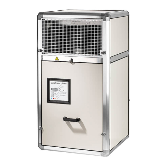
TKS models Overview This is an overview of the various TKS installation alternatives TKS 60 Indoor floor Indoor wall outdoor (option) Air flow Indoor floor Indoor wall outdoor (option) -
Page 7: Technical Data Tks 60
Technical data TKS 60 Free cooling perfor- The table below shows the performance of the free cooling unit: mance Specification 230 V –B ver. 48 V DC M5 filter F7 filter M5 filter F7 filter Air flow m 4285 4010... -
Page 8: Dimensions
Dimensions Dimensional diagram The diagram below shows the dimensions of the free cooling unit: TKS 60 Handle This unit has been equipped with one handle that can be secured using a padlock. In order to open the unit, the handle must first be folded out... -
Page 9: Mount Filter
Mount filter Fit sealing strips 35 mm... - Page 10 Mount filter, continued...
-
Page 11: Installation
Installation Installation, Dimen- sional diagram wall, outdoor Fit sealing strip outdoor only (cable tie) - Page 12 Installation, cont. Installation, Dimen- sional diagram floor Fit sealing strip Continued overleaf...
- Page 13 Installation, cont. Installation, Dimen- sional diagram wall, Indoor Continued overleaf...
- Page 14 Installation, cont...
- Page 15 Controller CC3000 Controller CC3000 rear 4 x Ø3mm Break away to integrate cable trays Fasten main part to the wall mount Accessconnectors Remove front cover to access connectors Use two screwsto secure the main part of the Press to release casing to the wall mount.
-
Page 16: System Setup
At startup insert SD card in the slot located on the side of the CC3000 controller. This will allow you to select the config file for your TKS 60. Note: When the SD card is inserted the controller will automatically update firmware. - Page 17 Controller CC3000 How to: Check correct installation After installation of controller and cooling product, correct connectivity can be checked by use of a selftest function. > See manual for CC3000. If automatic sequence is started, controller will activate all outputs one by one. Time duration for each step is 3 minutes, which should be sufficient for the installer to check that fans, dampers, air conditioners, heaters and alarms are...
- Page 18 Electrical diagram – CC3000-AC...
- Page 19 TKS60 -230C AC Connection of fan alarm TKS60 230V AC. Electrical diagram – CC3000 Default Cooling strategies (can be changed using the CC3000 controller). Free cooling mode Connect wire from fan to pin 5 and 6...
-
Page 20: Default Cooling Strategies (Can Be Changed Using The Cc3000 Controller)
Control strategi Default Cooling strategies (can be changed using the CC3000 controller) Free Cooling Mode Description Value Temperature when fan stops Temperature when Fan starts Min °C Temperature at bottom of P-band Max °C Temperature at top of P-band Set Point The wanted indoor temperature;... - Page 21 Standard Mode (Freecooling <> A/C) Description Value Temperature when fan stops Temperature when Fan starts Min °C Temperature at bottom of P-band Max °C Temperature at top of P-band Set Point The wanted indoor temperature; fan speed will be adjusted be- tween Min°C and Max °C A/C 1 on External Air Con unit 1 start if con-...
- Page 22 Energy save Mode (Freecooling > A/C) Description Value temperature when fan stops Temperature when Fan starts Min °C temperature at bottom of P-band Max °C Temperature at top of P-band The wanted indoor temperature; Set Point fan speed will be adjusted be- tween Min°C and Max °C A/C 1 on External Air Con unit 1 start if connected...
- Page 23 Air conditioner mode Description Value Set Point External Air Con unit 1 start if con- nected A/C 1 off External Air Con unit 1 stops if con- nected A/C 2 on External Air Con unit 2 start if con- nected A/C 2 off External Air Con unit 2 stops if con- nected...
- Page 24 Servicing interval Dantherm recommends the unit to be serviced at least once a year. We also recommend that the unit is inspected during the initial service to determine if the servicing interval is too long.
-
Page 25: Spare Parts List
Spare parts list Spare parts & The list of spare parts and their item numbers is shown below accessories TKS 60 Spare part Type Item number Fan 48VDC R3G355-RP23-XL 087365 Satellite PCB 48V DC 093713 10 pcs. Fuse 58V DC 110 Amp... -
Page 26: Function Test
Function Test Introduction After connecting the free cooling unit, the display normally shows the current room temper- ature. The following test must be carried out to ensure that the system works. Each test phase must be acknowledged with a signature and a date. This is to maintain the warranty and to pro- vide documentation prior to future servicing. - Page 27 Function Test, cont. Step Time Activity Result Alarm 5, low supply voltage 42VDC NC, check it is change to NO (multimeter) Alarm 6, high voltage 60VDC NC, check it is change to NO (multimeter) Alarm 7, Room temperature sensor NC, check it is change to NO (multimeter) Alarm 8, Outdoor temperature sensor NC, check it is change to NO (multimeter) Alarm 9, high temperature alarm (40°C)
- Page 31 Dantherm can accept no responsibility for possible errors and changes. Irrtümer und Änderungen vorbehalten. Dantherm n’assume aucune responsabilité pour erreurs et modifications éventuelles. Dantherm se exime de cualquier responsabilidad por errores y cambios realizados. A Dantherm recusa qualquer responsabilidade relacionada com eventuais erros e alterações.
- Page 32 Dantherm A/S Marienlystvej 65 7800 Skive Denmark www.dantherm.com service@dantherm.com...
Need help?
Do you have a question about the TKS 60 and is the answer not in the manual?
Questions and answers