Table of Contents
Advertisement
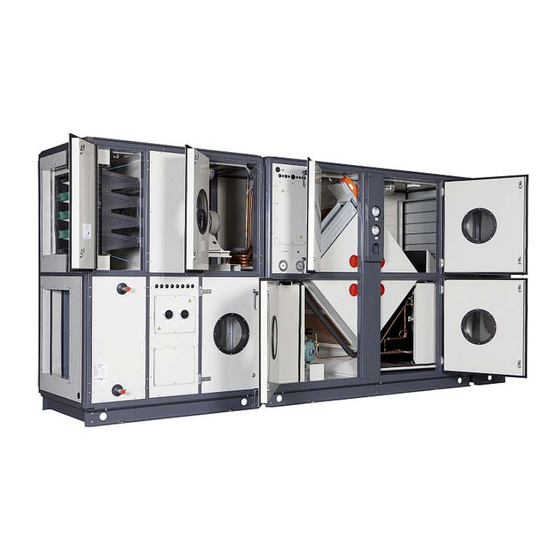
DanX for swimming pools
Transport, installation, commissioning
and service manual
EN
No. 961403 • rev. 1.0 • 01.10.2010
Der tages forbehold for trykfejl og ændringer
Dantherm can accept no responsibility for possible errors and changes
Irrtümer und Änderungen vorbehalten
Dantherm n'assume aucune responsabilité pour erreurs et modifications éventuelles
Advertisement
Table of Contents

Related Manuals for Dantherm DanX 2/4 XKS


Summary of Contents for Dantherm DanX 2/4 XKS
- Page 1 No. 961403 • rev. 1.0 • 01.10.2010 Der tages forbehold for trykfejl og ændringer Dantherm can accept no responsibility for possible errors and changes Irrtümer und Änderungen vorbehalten Dantherm n’assume aucune responsabilité pour erreurs et modifications éventuelles...
-
Page 3: Table Of Contents
0. TABLE OF CONTENTS 1. General 1.1 Introduction 1.2 Foundation for the unit 1.3 Minimum distances 2. Transportation 2.1 Unloading 2.2 Lifting with a forklift 2.3 Lifting with a crane 2.4 Storage 3. Installation 3.1 Introduction 3.1.1 Unit construction DanX – XWPS 3.1.2 Unit construction DanX –... - Page 4 0. TABLE OF CONTENTS 4.3 Plug fan 4.3.1 Frequency converter setup 4.3.1.1 Display mode 4.3.1.2 Quick menu 4.3.2 Air volume measurement and setting 4.3.3 Pressure transducer 4.4 XWPS section 4.4.1 Cooling circuit 4.4.2 Dampers 4.5 XK/XKS section 4.5.1 Internal mixing box XKS 4.5.2 Dampers XK 4.6 Frost thermostat 4.7 Filter pressure transmitter...
-
Page 5: General
1. GENERAL 1.1 Introduction The DanX type XWPS, XKS and XK equipment is designed for the use for ventilation, humidity and temperature control in private and public swimming pool areas. The use of the unit includes the required inspection and maintenance for these units, which is described in the back of this manual. -
Page 6: Transportation
• Check the packing and modules for transport damage and report immediately any • damage to the driver and to Dantherm Air Handling. Retain the packing until the sections/modules are placed on the mounting location to • avoid damages on cabinet parts or connecting pieces that overhang. -
Page 7: Lifting With A Crane
2. TRANSPORTATION 2.3 Lifting with a crane Never walk under a module when it is lifted with a crane. There is always a risk that the crane or helping material may break and cause serious injuries or death. Please be aware of the following general points: Only use a hoist that can manage the weight of the module! •... -
Page 8: Installation
3. INSTALLATION 3.1 Introduction There are three basic models of DanX units for swimming pool ventilation. Your DanX unit may differ a little from these. If you are in doubt how to assemble the modules, please ask you supplier for an exact drawing of the unit. Please refer to the type plate on the inspection side of the unit to find out if it is a XWPS or XK(S) unit you are about to install. -
Page 9: Unit Construction Danx - Xks
3. INSTALLATION 3.1.2 Unit construction DanX – XKS with integrated mixing box The DanX – XKS consist of a cross flow heat exchanger with an integrated mixing box. From left to right the unit consists of the following components/modules: Heating coil with supply air fan below*. Return air fan and return air filter above. -
Page 10: Installation Of Modules
3. INSTALLATION 3.2 Installation of modules Before placing the single modules in the right order, accordingly to chapter 3.1 the wooden crossbeams or pallets have to be removed and the separate delivered feet mounted on the base frame. To do so the following has to be done: Unwrap the module, open the inspection door and take out the separate box with the •... -
Page 11: Modules Side By Side
3. INSTALLATION 3.2.1 Modules side by side After placing all bottom modules in the right order on the floor, the modules must be assembled. If the unit includes halve height modules, install the bottom modules before the top modules. Follow these steps for mounting the modules: Adjust the height of the modules with the adjustable feet, so that all modules are in •... -
Page 12: Modules Above Each Other
3. INSTALLATION 3.2.2 Modules above each other After the installation of the bottom modules (se chapter 3.2.1) the halve height top modules can be placed above the bottom modules in the following way. Lift the module with a fork lift and push the module from the wooden pallet onto the •... -
Page 13: Duct Mounting
3. INSTALLATION 3.2.4 Duct mounting The ducts connected to the AHU must be suspended or underpinned with support elements as the duct connection panel of the unit is not strong enough to hold the duct work. The ducts can be connected to the DanX with flexible connections (optional accessory) to suppress vibrations of the unit. -
Page 14: Installation And Connection Of Components
3. INSTALLATION 3.3 Installation and connection of components All components and duct work of the air handling unit must be installed correctly before starting up and commissioning the DanX unit. Installation and connection work should only be carried out by trained specialists or by people supervised by authorized staff. -
Page 15: Condensed Water Outlet
3. INSTALLATION 3.3.2 Condensed water outlet Drainage from the condensate tray is taking place through a connection in front of the inspection side through the cover panel. On a XWPS unit will be three condense outlets, two on the exhaust side (negative pressure) and on the supply side (positive pressure). On XKS and XK units we will see one outlet, both on the exhaust side (negative pressure). -
Page 16: Flow Gauges For Centrifugal Fans
3. INSTALLATION 3.3.5 Flow gauges for centrifugal fans The flow gauges for centrifugal fans are mounted at the front of the XWPS, XKS or XK module and prewired to the terminal strip of the module. After assembling the unit the pressure tubes have to be connected to the probes in the fan section. -
Page 17: Frequency Converter For Plug Fans
It is the responsibility of the user or installer to ensure correct earthing and protection in accordance with national and local standards. Frequency converters delivered by Dantherm Air Handling are found in the fan section, where they are stored under transport. -
Page 18: Water Cooled Condenser
The drawing below shows Dantherm’s suggestion on how to connect the water cooled condenser to the swimming pools water supply. -
Page 19: Lphw Coil
3. INSTALLATION 3.3.10 LPHW coil The supply is always connect to the bottom of 1 and 2 row LPHW coils, as this makes it easy to bleed the coil for air. If the coil is larger than 2 rows, the water and air flow must be counter flow to obtain the calculated heat capacity. -
Page 20: Commissioning
4. COMMISSIONING 4.1 Introduction When servicing on air handling units always turn off the electricity on the main switch and the repair switch (complete shut down) and secure for reconnection from unauthorized persons. Only open the inspection doors when the unit is totally stopped and the fans have come to a stop. -
Page 21: Unit Function Danx - Xks
4. COMMISSIONING 4.1.2 Unit function DanX – XKS with integrated mixing The DanX – XKS consist of a cross flow heat exchanger with integrated mixing. The DanX XKS is using a minimum outdoor air which is required for hygienic reasons in the pool hall. -
Page 22: Centrifugal Fan
4. COMMISSIONING 4.2 Centrifugal fan To commission the centrifugal fans for the first time, the following actions have to be taken: Check if the transportation brackets have been removed. • Check by hand if the fan wheel is turning freely. •... - Page 23 4. COMMISSIONING If the measured air volume does not correspond to the type plate data, or when the measured running current of the motor is too high, the fan transmission has to be changed. After calculating the right pulley seizes the pulleys can be changed in the following way. Unscrew the two Allen screws (3) and pull off the pulley (2) by screwing one Allen •...
-
Page 24: Plug Fan
4. COMMISSIONING 4.3 Plug fan To commission the plug fans for the first time, the following actions have to be taken: Check that the four measuring probes below the pressure transmitter are blanked. • Check if the transportation brackets have been removed. •... -
Page 25: Display Mode
4. COMMISSIONING 4.3.1.1 Display mode In normal operation, one item of operating data can be displayed continuously at the operator's own choice. By means of the [+/-] keys the following options can be selected in Display mode: Output frequency [Hz] •... -
Page 26: Pressure Transducer
4. COMMISSIONING If you want to lower the air volume to 4000 m /h you have to change parameter 215 (air volume min set point) in the frequency converter. The calculation for the value is done with the following formula: Value = Where Par205 is parameter 205 (Max pressure transducer setting, see 4.3.3) and k the nozzle coefficient. - Page 27 4. COMMISSIONING If the green LED is flashing you have to change the pressure range setting. Change of setting can be done with the DIP switch 1-3 (2). This can be the case if you run with a higher or lower air volume than first designed. The pressure range depending on the DIP switch setting can be seen below.
-
Page 28: Xwps Section
4. COMMISSIONING 4.4 XWPS section To commission the XWPS section for the first time, the following actions have to be taken: Check if the drop bridge between the two modules has been installed (see 3.3.1) • Check if the drain pipes have been installed correctly (see 3.3.2) and if the drip trays •... -
Page 29: Dampers
4. COMMISSIONING 4.4.2 Dampers You will find the following 5 dampers installed in a XWPS section: 1. Dehumidification damper 2. By-pass damper 3. Recirculation damper 4. Outdoor air damper 5. Exhaust air damper Before commissioning the unit make sure that the dampers are opening/closing in the right direction. -
Page 30: Internal Mixing Box Xks
4. COMMISSIONING 4.5.1 Internal mixing box XKS You will find the following 4 dampers installed in a XKS section: 1. Exhaust air damper 2. Recirculation damper 3. Outdoor air damper 4. By-pass damper Before commissioning the unit make sure that the dampers are opening/closing in the right direction: Set the controls to night time (no outdoor air) and make sure that there is a temperature difference between the swimming pool hall temperature set point and the outside air... -
Page 31: Dampers Xk
4. COMMISSIONING 4.5.2 Dampers XK You will find the following 4 dampers installed in a XK and mixing box section: 1. By-pass damper 2. Exhaust air damper 3. Recirculation damper 4. Outdoor air damper Before commissioning the unit make sure that the dampers are opening/closing in the right direction: Set the controls to night time (no outside air) and the dampers will be in the following positions:... -
Page 32: Maintenance
5. MAINTENANCE 5.1 Introduction For optimum operation conditions and a long product life it is necessary to perform preventive maintenance on various parts within the stipulated intervals (see 5.2). When servicing on air-handling unit always turn off the electricity on the main switch and repair switch (complete shut down) and secure for reconnection from unauthorized persons. -
Page 33: Fans
5. MAINTENANCE 5.4 Fans The following general steps should be taken to maintain the fans: Check the fan wheel for unbalance (every 3 month). • Check the fan and motor bearings for unusual noise (every 3 month). • Check vibration dampers for damage (every 3 month) •... -
Page 34: Filter
5. MAINTENANCE 5.5 Filter If the filters are equipped with a pressure transducer the control panel automatically gives an alarm when the filters have to be changed. Still every 6 month the filters should be checked for damage/leakages which will not be detected by the pressure transmitter. If no pressure transmitter is installed the following steps should be taken every 6 month: Check the filter for dirt and damage. -
Page 35: Dampers
If you are in doubt about the condition of the cooling circuit, stop the compressor at once to avoid damage and call a cooling technician or the Dantherm service. 5.10 Drop catcher The following steps should be taken to maintain the drop catcher: To get access to the drop catcher, remove the outer cabinet panel and the inner air •... -
Page 36: Faultfinding
6. FAULTFINDING 6.1 Introduction Normally an operation fault will give an alarm in the display of the control panel. The alarm messages may be named differently. For details, please refer to the manual of the control panel. If the frequency converter for the fan is showing an alarm, please refer to the manual of the frequency converter. - Page 37 6. FAULTFINDING If the frost thermostat is manual, it must be you have to reset before starting the unit. The thermostat is located in the compartment (1) above the LPHW heating coil. The fire thermostat must be reset before the unit is started again. Press the red button on the thermostat to reset.
-
Page 38: Disposal
7. DISPOSAL 7.1 Disposal of the unit Removal and disposal of the unit may only be performed by professionals. All supply lines like electricity and hot water must be shut down before decommissioning and dismantling the equipment. Make sure that no water-glycol mixture is leaking. Empty the heating coil for the water-glycol mixture before removing it from the unit. -
Page 39: Appendix
8. APPENDIX 8.1 VLT 2800 parameter settings two speed with pressure transducer Parameter Description Value Function / unit Comment Configuration Process closed loop Torque characteristic Variable torque medium Motor power * See motor type plate Motor voltage Motor frequency Motor current * See motor type plate Motor speed * See motor type plate...
Need help?
Do you have a question about the DanX 2/4 XKS and is the answer not in the manual?
Questions and answers