Table of Contents
Advertisement
Quick Links
Advertisement
Table of Contents

Related Manuals for Dantherm Combo Cooling 6000/900


Summary of Contents for Dantherm Combo Cooling 6000/900
- Page 1 Combo Cooling 6000/900 Service manual Rev. 1.0...
- Page 2 Der tages forbehold for trykfejl og ændringer Dantherm can accept no responsibility for possible errors and changes Irrtümer und Änderungen vorbehalten Dantherm n’assume aucune responsabilité pour erreurs et modifications éventuelles Dantherm no asume ninguna responsabilidad sobre posibles errores o modificaciones...
-
Page 3: Table Of Contents
Copying of this service manual, or part of it, is forbidden without prior written permission Copyright from Dantherm A/S. Dantherm reserves the right to make changes and improvements to the product and the Reservations service manual at any time without prior notice or obligation. -
Page 4: Warning
• Face shield • Proper work attire (long sleeve shirt and long pants) Please strictly observe the following: Special Skill is required to install the Dantherm products. Non-qualified personnel should not attempt any of the actions shown in this installation guide. -
Page 5: Product Description
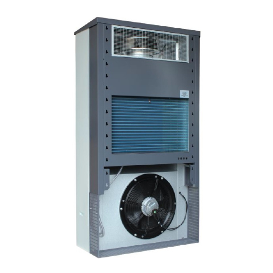
The Combo Cooling series is designed to control the internal temperature of an outdoor enclosure. Combo Cooling series removes dissipated heat from electronic equipment and it´s designed to maintain correct temperature for electronic equipment. Dantherm recommends that the cooling system should be running continuously! Important This table shows the accessories available from supplier... - Page 6 Overall description, continued Outdoor view This illustrates the units outdoor view: Fig. 1 This table refers to the outdoor view above Description Outdoor parts Pos . Description Free cooling air inlet Condenser cooling air output Front door with lock Removable side cover for service access. Condenser air inlet.
- Page 7 Overall description, continued Indoor view This illustrates the units indoor view: Fig. 2 This table refers to the outdoor view above Description Indoor parts Pos . Description Free cooling supply air inlet Return air Cable routing, option 1 Cable routing, option 2 Removable installation bracket Condenser fan...
- Page 8 Overall description, continued This illustrates the units key components: Exploded view Fig. 3 Description This table refers to the parts view above exploded parts Pos . Descriptions Free cooling fan Wall bracket frame Embedded controller, type CC4 Free cooling filter AC/free cooling operation shift damper Cable routing path AC condenser...
- Page 9 Overall description, continued Cooling The illustration and table below show the airflows of Combo Cooling. functionality The unit is combining free cooling and active cooling, to obtain the target temperature inside the shelter application with lowest possible energy consumption. The different cooling modes are: 1.
-
Page 10: Electronic Control Strategy
Electronic control strategy Introduction This section describes the key functionallity of the embedded CC4 controller. For a complete description, Dantherm issues upon request, an extended manual for the controller. Never carry out any installation, maintenance or service, without disconnecting the power WARNING supply (please notice that this units has dual power source AC &... -
Page 11: User Guide
OR insert an SD card with a config file, and this config file will be automatically uploaded and initiated on the fly. Dantherm STRONGLY recommends to use the Dantherm RS485 external display. This has a Display unit... -
Page 12: Installation
Installation The ComboCooler unit needs proper installation in order to operate flawless for many years. Introduction Please follow this section for installation • Never carry out any installation, maintenance or service, without disconnecting the power WARNING supply (please notice that this units has dual power source AC & DC), by means of the Warning external power supply disconnecting devices. - Page 13 Installation, continued Pre-installation Please reserve exempted space for service as shown below. considerations 400 mm 400 mm 1440 mm Fig. 6 Please make sure, that one of the two shown cable run options is achievable. Standard option - needs drilling holes in wall in center to the units holes Alternative option- route the cable in free air space if needed...
- Page 14 Installation, continued Cut two retangular holes with appropiate tools, according these below measures Cut-out Please consider drilling the correct amount of cable inlets. Warning Caution min. 90 mm 275 mm 800 mm 323 mm 800 mm 500 mm 25 mm 364 mm 30 mm 30 mm...
- Page 15 Installation, continued Mounting unit onto Place the unit onto the bracket by means of a forklift or similar lifting device. bracket Fig. 10 Mount the four bolts, securing the unit to the frame, and seal the edges between unit and Secure and seal wall according illustration 4x DIN 10...
- Page 16 Installation, continued Indoor sensor Route the room sensor to an indoor location, where the temperature wants to be controlled. Please make sure the sensor isn’t blocked or touching any metal, and isn’t placed in the air stream coming from the ComboCooler. Fig.
-
Page 17: Electrical Connections
Electrical connections External This below illustration shows the pin assignment for connections: External safety breaker External safety breaker connections (not included) (not included) 48V DC negative 48V DC negative 48VDC 48VDC 10A Mini blade terminal. 16A fused 48V DC positive 16A fused 48V DC positive FX ”Littlefuse”... - Page 18 J4 - damper 2 The damper output feeds the damper motor with 40-60Vdc/ max. 100mA J16 / 17 - RS 485 RS485 – RTU Modbus. J17 can supply the Dantherm display unit with power. Communication data: baud rate - 9600...
-
Page 19: Alarm Out
Alarm out Introduction In order to create the correct functionality on any hardwired alarm/digital in connections, the corresponding parameter, needs to be set up correct. After connecting the wires to the output terminals, please enter the parameter setting Alarm out routing through the SD card. -
Page 20: Digital Inputs
Digital inputs Digital input After connecting of the wires, to the input terminals, please initiate parameter settings through SD card. Both digital inputs can control and force a certain operation or request. These are some of the possibilities: • Shutting down in case of a fire. •... -
Page 21: Operation Errors
Operation errors Introduction To prevent damaging the cooling system, as well as protect the radio equipment installed into the enclosure, the unit has a real time protection system, that runs permanently. Error handling Any detected operation error will: • Flashes the red LED located next to the SD card interface. •... -
Page 22: Service Guide
Service Guide Preventative maintenance Preventive maintenance has to be carried out to: Introduction • Continues operation in specified range • Avoid malfunctions • Avoid inefficient operation • Maximize the unit’s lifetime The factory warranty is only valid if documented preventive maintenance has been carried out, with an time interval of: •... -
Page 23: Cleaning
Cleaning Filter should be changed if it shows sign of degeneration or clocking. Please notice that the Free cooling unit is equipped with a pressure differential switch indicating that the filter has a pressure maintenance drop of 150Pa, equal to 2/3 of capacity used. To change filter please follow below procedure Step Action... -
Page 24: Inspection
Inspection The unit must be inspected prior to any reassemble and put back into service. Inspection Please follow below steps Phase Description Are the fans clean and free of any corrosion? Are the coolant pipes free of obstructions, damage, corrosion and show no obvious signs of leakage? Are the coil lamellas clean and undamaged? Are all fan blades free of any obstructions, cracks or missing blades? -
Page 25: Schematics
Schematics This schematics shows the units schematics Introduction... -
Page 26: Spareparts
Spareparts This illustrates all available spareparts. Illustration Spare parts list Pos . Description Order no . Evaporator fan 012848 CC4 controller 075255 Damper motor 48V DC 075254 Condenser fan 230V AC - EC type 075250 Compressor 1-phase 230V AC 50Hz 220470 RS 485 external display module 075210... -
Page 27: Technical Data
Technical data Overall specification This below table, shows the units main specifications. Dimensions, weight & mounting Unit dimensions (height×width×depth) 1997 x 1072 x 527 Single packing dimensions (height×width×depth) 2180*1145*660 (wooden package) Net weight Single package weight incl. unit Mounting method Separate frame Controller location/interface RS485 ModBus and... - Page 28 Technical data, continued Cable and breaker This table shows the cable and circuit breaker specification Voltage 230V/50Hz . 48V DC Circuit Breaker Wire Size 2,5mm2/12AWG 2,5mm2/12AWG These illustrations shows the units dimensions in millimetres Dimension Fig. 16...
- Page 29 Technical data, continued Dimensions in Inch . These illustrations shows the units dimensions in inch. Fig. 17...
-
Page 30: Declaration Of Conformity
Declaration of Conformity Dantherm hereby, declare that the unit mentioned below: Declaration of Conformity No.: 367506 Type: ComboCooler 6000/600 complies with the following directives: 2006/42/EC Directive on the Safety of Machines 2006/95/EC Low Voltage Directive 2004/108/EC EU EMC Directive (December 2004) - Page 31 NO 918 348 328 MVA England China Dantherm Air Handling Ltd. Dantherm Air Handling Inc. Dantherm Air Handling (Suzhou) Co., Ltd. 12 Windmill Business Park 110 Corporate Drive, Suite K Bldg#9, No.855 Zhu Jiang Rd., Windmill Road, Clevedon Spartanburg, SC 29303...
- Page 32 Dantherm Air Handling A/S Marienlystvej 65 7800 Skive Denmark www.dantherm.com service@dantherm.com...
Need help?
Do you have a question about the Combo Cooling 6000/900 and is the answer not in the manual?
Questions and answers