
Related Manuals for Dantherm AC-M5 W MKII


Summary of Contents for Dantherm AC-M5 W MKII
- Page 1 AC-M5 W MKII Service manual No. 062367 • rev. 1.0 • 15.02.2011 Betjeningsvejledning DVC-styring Side User’s guide for the DVC controller Page...
- Page 2 Der tages forbehold for trykfejl og ændringer Dantherm can accept no responsibility for possible errors and changes Irrtümer und Änderungen vorbehalten Dantherm n’assume aucune responsabilité pour erreurs et modifications éventuelles...
- Page 3 Introduction Overview Introduction This is the service manual for the Dantherm Air Handling A/S AC-M5 W MKII unit. The below table of contents gives an overview of the main sections. Serial number This manual covers units with serial numbers equal or higher than:...
- Page 4 Copying of this service manual, or part of it, is forbidden without prior written permission from Dantherm Air Handling A/S. Reservations Dantherm Air Handling A/S reserves the right to make changes and improvements to the product and the service manual at any time without prior notice or obligation. EC-Declaration of...
- Page 5 Syntax Introduction All products are named according to a syntax giving information about the specific unit configuration. Example This example is not necessarily related to the specific unit this manual describes: AC-M5W-H070-B-225-R6014-G3F7-SH-X1 Air conditioner Heater (diesel) Military unit 5 kW nominal performance Window mount Split unit Electric heat...
- Page 6 Product description Overview Introduction This section will give you a description of the AC-M5 W MKII and its functionality. Content The section covers the following topics: Topic See page General description Description of the cooling system Description of the control board...
- Page 7 Typical applica- The AC-M5 W MKII is designed to be built into a trap door system, which is mounted in tions the container. Optionally in welding frame.
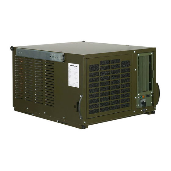
- Page 8 General description, continued Cabinet The unit is a strong construction made in 0.9 mm sheet metal plates, which are galvanised and protected against corrosion. Outside finish painting is standard NATO green, RAL6014 with infrared anti-reflecting qualities. The condensate drain is located un- der the unit.
- Page 9 Land Class C Noise level, described in DEF- STAN-59-411. As the AC-M5 W MKII is unavailable with fresh air intake the air being processed in this unit is re-circulated air within the shelter.
- Page 10 (above 60 °C) the cooling of the condenser airflow will be too low, and the high pressure results in cut out of the HP pressure switch. Illustration This illustrates the cooling system and internal compo- nents of the AC-M5 W MKII: Continued overleaf...
- Page 11 Description of the cooling system, continued Parts and their This table gives an overview and short description of each part shown in the previous illus- function tration: Part Function Evaporator Absorbs heat from the shelter by cooling down the circulated Condenser Emits the heat generated in the tent/room to the outside air Centrifugal fan...
- Page 12 The control panel on the front side contains all the controls required for normal opera- tion. Illustration This illustrates the control board of the AC-M5 W MKII: Part/function This table gives an overview of each part of the control panel:...
- Page 13 Description of the control board, continued Part/function, con- Part Function tinued Indicator On the operator panel there are 4 control lamps, indicating the lamps following from left to right: Symbol Color Description IR connection to serial port. For Dan- therm service technician only Green Cooling circuit is operating to lower tem- perature.
- Page 14 Accessories Introduction Further information about each separate accessory is available upon request to Dantherm Air Handling A/S. List Below you will find a complete list with drawings, description and article numbers of available accessories: Article No./ Accessory Illustration Description NSN No.
- Page 15 Warning: The evaporator fan will run according to speed selector, even with the mode selector in “0” OFF position, if temperature inside the AC-M5 W MKII cabinet exceeds 50 °C. This will automatically shut down when temperature inside the AC-M5 W MKII cabinet drops below 35 °C...
- Page 16 DO NOT cycle the temperature dial as this will cause the cooling to NEVER come Contents This section contains the following topics: Topic See page Make the AC-M5 W MKII ready for use ACU removal Starting up and shutting down the air conditioner Transport and lifting of the unit...
- Page 17 Make the AC-M5 W MKII ready for use Tools List of tools required: • 5 mm Allen key • TX 15 screwdriver • 10 mm spanner or socket wrench Trap door system Read this recommendation before installing the trap door:...
- Page 18 Make the AC-M5 W MKII ready for use, continued Trap door system, Follow these steps to install the unit in the door trap system continued Step Action Loosen the 21 screws that hold the front grill. Dismount the front grill and the...
- Page 19 Make the AC-M5 W MKII ready for use, continued Trap door system, Step Action continued Screw in loosely the two 8 mm finger screws dangling in wires on each horn. This is to secure the ACU while re-mounting the front grill. It is...
- Page 20 Make the AC-M5 W MKII ready for use, continued Trap door system, Step Action continued Next mount the buffer consoles. One for each side Connect power Re-mount the door of the trap door system and shut it securely using the...
- Page 21 ACU removal Procedure Follow this procedure to remove the ACU: Step Action Switch off the ACU and remove the power cable from the shelter connection Ensure ACU is in the filter change/service position, with the securing knobs loosely fitted in the large holes in the horns Unscrew the 19 torx 15 screws and detach the front grill of the unit Remove the filter and the exhaust/discharge grill Do not harm the EMC seal in the front grill...
- Page 22 Starting up and shutting down the air conditioner Warning Cycling the temperature dial up and down rapidly will cause the cooling circuit not to start. This is due to a start up delay of the compressor built in to the controller. Before starting up Before starting the AC M5W, the unit has to be brought into the deployed position.
- Page 23 Starting up and shutting down the air conditioner, continued Fault, continued • Compressor thermo relay: Running current for the compressor is too high • OT thermostat (only in models with heating installed): High air temperature, or non-operating evaporator fan has stopped the heating coil Refer to the “Fault finding guide”, page 33 for possible solutions.
- Page 24 Transport and lifting of the unit Transport of the The units are delivered, stacked and unit strapped to a pallet. Stack maximum 3 on a euro pallet. DO NOT STACK OTHERWISE Lifting of the unit By means of a forklift is possible to lift the unit to the right height and to push it into the trap door system from the outside of the container.
- Page 25 Service guide Overview Serial numbers This section gives the necessary information to help the responsible maintenance per- sonnel at servicing and repairing the air conditioner. All requests for information, service or parts should include the serial number. Product model and serial numbers are available from the data plate which is located on the right side of the unit.
- Page 26 Preventive maintenance Introduction In order to achieve the best possible operation and long lifetime of the air conditioner it has to be maintained properly within defined guide lines. This section contains the description of daily, monthly and annual maintenance. Tools For service and maintenance a torx 15 screwdriver and a 10 mm spanner or socket wrench is required.
- Page 27 Preventive maintenance, continued Monthly preven- Please follow this procedure to do monthly preventive maintenance or every 200 hours tive maintenance of operation: Caution When dismounting the front cover you are breaking the EMC seal. When remounting the unit be aware that the EMC seal is intact and restored properly. Step Action Perform daily maintenance...
- Page 28 Preventive maintenance, continued Annual preventive Follow this procedure to carry out the annual preventive maintenance: maintenance Caution When dismounting the front and the top cover you are breaking the EMC seal. When remounting the unit be aware that the EMC seal is intact and restored properly. Step Action Perform the daily and monthly maintenance, see above...
- Page 29 • Dantherm Air Handling A/S spare parts number/text • NATO stock number of parts • Dantherm Air Handling A/S field unit type • Dantherm Air Handling A/S production and serial number from the data plate of the field unit (or approximate date of delivery). Information Not every item will be available for delivery individually, if it is part of a group naturally forming a whole or part of a purchased, complete component.
- Page 30 Spare parts, continued Illustration Available spare parts for the Spare parts: Fig. 2 Continued overleaf...
- Page 31 Spare parts, continued List List of spare parts for the Spare parts: Index No. Part No. Nomenclature NATO No. 063108 Cover complete with insulation 1670-22-620-0246 063109 Evaporator coil 4130-22-620-0248 066668 Heating 2000 W complete 4520-22-620-0249 Fan and fan housing complete, 4120-22-620-0312 063111 evaporator...
- Page 32 Spare parts, continued List, continued Index No. Part No. Nomenclature NATO No. 063137 Control, printed circuit board 5998-22-620-0281 063138 Control box, cover 5340-22-620-0282 063139 Copper tube set 4710-22-620-0296 063140 EMC seal complete, 2 pcs. 4120-22-620-0311...
- Page 33 Fault finding guide Fault finding Malfunctions that might occur in the operation of the air conditioner are listed in the ta- ble below. Reference to actions required to restore the air conditioner to normal operat- ing condition are also indicated. If the air conditioner should malfunction, find the problem in column 1.
- Page 34 Fault finding guide, continued Fault finding, con- Problem Cause Action tinued No heating action possi- Overheat thermostat failure Allow temperature to drop ble. or loose electrical connec- before pressing the reset tion button on top of ACU Power light is green. Heat indicator lamp is red.
- Page 35 Hotline The After Sales Support Department of Dantherm Air Handling A/S is ready to help you in case of a problem. To be able to offer quick and efficient help, please have the following information ready when contacting Dantherm Air Handling A/S: •...
- Page 36 Technical information Overview Contents This section covers the following topics: Topic See page Technical data Dimensions Wiring diagram References for the wiring diagram...
- Page 37 Technical data Introduction Technical data for the AC-M5 W MKII unit. Performance The air conditioner has a maximum cooling capacity of 4.7 kW. characteristics When the relative humidity of the air inlet is high, the air can be cooled below its dew point and thus condense some of the water vapour to free water.
- Page 38 Dimensions Illustration This illustrates the unit dimensions (mm):...
- Page 39 Wiring diagram Wiring diagram, a This is the wiring diagram for the unit, references are available on page 41: Continued overleaf...
- Page 40 Wiring diagram, continued Wiring diagram, b...
- Page 41 References for the wiring diagram References The references refer to the wiring diagram: Reference Description Electrical heat 2x1000 W/230 V Compressor ZR 22 K3E-PFJ RC unit 470n + 47R X2 Capacitor for compressor 40 MF/400 V Condenser fan EBM A4E350 Capacitor for condenser fan Condensate pump Blue Diamond Capacitor for evaporator fan 5mF/450 V low speed...
Need help?
Do you have a question about the AC-M5 W MKII and is the answer not in the manual?
Questions and answers