Advertisement
Advertisement

Related Manuals for Dantherm VA-M40 MKII


Summary of Contents for Dantherm VA-M40 MKII
- Page 1 VA-M40 MKII Service manual Rev. 2.2...
- Page 2 Der tages forbehold for trykfejl og ændringer Dantherm can accept no responsibility for possible errors and changes Irrtümer und Änderungen vorbehalten Dantherm n’assume aucune responsabilité pour erreurs et modifications éventuelles...
- Page 3 Overview Introduction This Dantherm portable heater has been designed and manufactured with high quality materials and care in workmanship. The instructions in this service manual have been prepared to ensure that, when followed, this portable heater will provide long and effi- cient service.
- Page 4 Safety and warning instructions Introduction Safety must always be the operator's prime concern. The operator must read and under- stand this manual and all safety signs on the heater before operating the equipment. Failure to follow these safety precautions could result in property damage and/or per- sonal injury or death.
- Page 5 Safety and warning instructions, continued Warning If, at any time, exhaust fumes or fuel odours can be detected in the space being heated or ventilated, shut the heater down immediately. If an external source of the fumes can- not be detected and eliminated the heater combustion chamber must be inspected for cracks or other defects.
- Page 6 Safety and warning instructions, continued Warning Location location and ex- Never operate the heater in a confined space without adequate ventilation. The heater haust fumes should be located externally, and the heat transferred to the shelter by the insulated flexible ducts. The location of the heater should avoid any possibility of ingesting ex- haust fumes from other sources such as vehicles, generators or other engines.
- Page 7 Copying of this service manual, or part of it, is forbidden without prior written permis- sion from Dantherm. Reservations Dantherm reserves the right to make changes and improvements to the product and the service manual at any time without prior notice or obligation. Part number The part number under which this service manual can be ordered is 971145.
- Page 8 Syntax Introduction All products are named according to a syntax giving information about the specific unit configuration. Example This example is not necessarily related to the specific unit this manual describes: AC-M5W-H070- B-225-R6014-X1 Air Conditioner Heater (diesel) Military unit 5 kW nominal performance Window mount Split unit heat option...
-
Page 9: Table Of Contents
Product description Overview Introduction This section will give a more detailed description of the VA-M40 MK II and its function- ality. The space heater can be split up into five basic systems, see the below topics for further information. Contents This section covers the following topics: Topic See page... -
Page 10: General Description
General description Purpose and field The Dantherm portable, duct type, heater model VA-M40 MK II is designed primarily to applications supply un-contaminated, heated air to tents and other types of temporary or portable shelters. In addition, the heater is suitable for various field applications such as the warming up of cold soaked equipment, engines, vehicles, aircraft, and other spot or space heating requirements. -
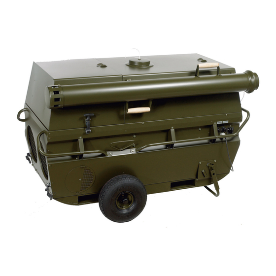
Page 11: Cabinet
Cabinet Cabinet The steel cabinet completely encloses the space heater components and systems. The powder painting finish is standard NATO green, RAL 6014. Illustration This illustrates the heater: Part Outlet openings Flue stack ... - Page 12 Cabinet, continued Duct openings The air outlet openings can be closed, when not in use, by covers secured with rubber straps, which are designed to be operated by personnel wearing protective gloves. Duct connections are provided for two tents, both supply and return air, making the heater suitable for either heating 100 % outside fresh air, or recirculating interior air.
-
Page 13: Combustion System
Combustion system Introduction This system consists of an oil burner , combustion chamber with heat exchanger , and the flue stack . Illustration This illustrates the combustion system: Part Flue stack Heat exchanger Inspection glass Oil burner ... -
Page 14: Air Circulation System
Air circulation system Illustration This illustrates the air circulation system: Part Heated air outlet Direct driven fan Air inlet Fresh air intake Fig. 3 Air circulation sys- The air circulation system consists of a direct driven fan and internal air passages from the air inlet ... -
Page 15: Fuel System
Fuel system Illustration This illustrates the fuel system: Part Fuel pump Flow control/De- Aerator Fuel pre-heater Filter/water separa- Oil lance Fig. 4 Fuel system Fuel is sourced externally from either a drum or jerry can, and is drawn by the burner pump to the burner through a fuel assembly starting with oil lance ... -
Page 16: Control System
Control system Control system The heater incorporates a control system that allows fully automatic operation after a start cycle has been initiated by the room thermostat. Safety devices will completely shut down ignition, fuel flow and fans in case of malfunction. All operating controls and components are mounted to permit easy access for operation, maintenance and trou- bleshooting. - Page 17 Control system, continued Room thermostat The room thermostat (accessory) will be placed inside the tent, to control the room temperature. The wanted temperature will be set on the thermostat. If the temperature falls below the set point the thermostat will automatically start up the burner. After reaching the set point the thermostat automatically shuts off the burner of the unit again.
- Page 18 Control system, continued , continued Color Indication CO failure Illuminates when a CO monitor is connected and a CO alarm has been detected. In this case the unit will stop totally and can only be started again after having pressed the reset button on the external CO monitor Power Green Illuminates when the power is connected to the unit...
-
Page 19: Accessories
Accessories Introduction There are different accessories available for the VA-M40 MK II which can be ordered di- rectly from Dantherm. You will find the part number or NSN for ordering in the spare part section on page 58. Accessories List of the available accessories:... - Page 20 User’s guide Overview Introduction This section will give a more detailed description about how to utilize the heater. The section contains all the necessary information which is needed to install, start up, run and store the unit. Contents This section contains the following topics: Topic See page Pre-planning...
Need help?
Do you have a question about the VA-M40 MKII and is the answer not in the manual?
Questions and answers