
Related Manuals for Pickering 40-200


Summary of Contents for Pickering 40-200
- Page 1 40-200 User Manual PXI CAN/FlexRay/Differential Bus Fault Insertion Switch pickeringtest.com Issue 2.8 April 2023...
- Page 2 © COPYRIGHT (2023) PICKERING INTERFACES. ALL RIGHTS RESERVED. No part of this publication may be reproduced, transmitted, transcribed, translated or stored in any form, or by any means without the written permission of Pickering Interfaces. Technical details contained within this publication are subject to change without notice.
- Page 3 Pickering Interfaces strives to fulfil all relevant environmental laws and regulations and reduce wastes and releases to the environment. Pickering Interfaces aims to design and operate products in a way that protects the environment and the health and safety of its employees, customers and the public. Pickering Interfaces endeavours to develop and manufacture products that can be produced, distributed, used and recycled, or disposed of, in a safe and environmentally friendly manner.
-
Page 4: Product Safety
If this product is heavy reference should be made to the safety instructions for provisions of lifting and moving. STATIC SENSITIVE To indicate that static sensitive devices are present and handling precautions should be followed. DIFFERENTIAL BUS FAULT INSERTION SWITCH 40-200 Page (IV) REED RELAY MODULE 40-110/115/120/125 Page (IV) -
Page 5: Table Of Contents
Pre Operation Checks ............3.1 Hardware Installation ............3.2 Software Installation .............3.2 Testing Operation ..............3.3 Section 4 Programming Guide ..............4.1 Programming Options For Pickering PXI Modules ....4.1 Module Architecture ..............4.2 Programming The Module ............4.6 Using Pickering Drivers in LabVIEW ........4.13 Section 5 Connector Information ..............5.1 Section 6 Trouble Shooting .................6.1... - Page 6 THIS PAGE INTENTIONALLY BLANK DIFFERENTIAL BUS FAULT INSERTION SWITCH 40-200 Page (VI)
-
Page 7: Warnings And Cautions
Not to be used in safety critical circuits, refer to the Pickering Interfaces’ terms & conditions of sale. This module must not be used for the switching of Mains Circuits. For the switching of voltages up to the module’s full specification, Secondary Circuit power supplies and the Device Under Test must... - Page 8 • For suitably equipped products in the event of an emergency press the red “emergency stop” button situated on the front of the unit. DIFFERENTIAL BUS FAULT INSERTION SWITCH 40-200 Page (VIII) 2 AMP 1-POLE UHD MATRIX MODULES 40-575 / 576 / 577 / 578 / 579...
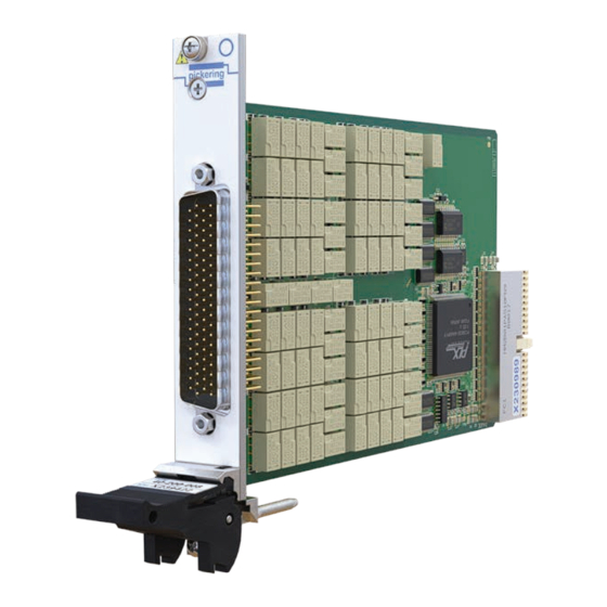
- Page 9 Supported by PXI or LXI Chassis y Supported by eBIRST ™ y 3 Year Warranty The 40-200 is designed to simulate common faults on two Pickering’s Range of PXI Fault Insertion Switches wire communication interfaces such as CAN Bus.
- Page 10 CH8 In CH8 Out CH4 In CH4 Out 2-Wire, 8-Channel Fault Insertion Switch Module 2-Wire, 4-Channel Fault Insertion Switch Module Switching Diagram (Part No. 40-200-008) Switching Diagram (Part No. 40-200-004) pickeringtest.com Page 2 DIFFERENTIAL BUS FAULT INSERTION SWITCH 40-200 Page 1.2...
- Page 11 +12 V -12 V 150 mA Mechanical Characteristics Single slot 3U PXI (CompactPCI card). 3D models for all versions in a variety of popular file formats are available on request. pickeringtest.com Page 3 DIFFERENTIAL BUS FAULT INSERTION SWITCH 40-200 Page 1.3...
- Page 12 2m length A078DMR-078DFR-9A200 Note: Other lengths and terminations are available, please contact your local Pickering Sales Office for details. For other connection accessories for the 40-200 modules please refer to the 90-006D 78-pin D-Type Connector Accessories data sheet where a complete list and documentation can be found for accessories, or refer to the Connection Solutions catalog.
- Page 13 • All chassis conforming to the 3U PXI and 3U Compact PCI (cPCI) specification • Legacy and Hybrid Peripheral slots in a 3U PXI Express (PXIe) chassis • Pickering Interfaces LXI or LXI/USB Modular Chassis Chassis Selection Guide Standard PXI or hybrid PXIe Chassis From Any Vendor: •...
- Page 14 1200+ products. We offer everything from simple mating connectors to complex cables assemblies and terminal blocks. All assemblies are manufactured by Pickering and are guaranteed to mechanically and electrically mate to our modules. These accessories are detailed in Connector Accessories data sheets, where a complete list and documentation can be found for each accessory.
- Page 15 Supporting Products & Software 40-200 Programming Pickering provide kernel, IVI and VISA (NI & Keysight) drivers which are compatible with all Microsoft supported versions of Windows and popular older versions. For more information go to pickeringtest.com/os The VISA driver support is provided for LabVIEW Real Time Operating Systems (Pharlap and Linux-RT). For other RTOS support contact Pickering.
- Page 16 To view, download or request any of our product resources go to pickeringtest.com/resources © Copyright (2023) Pickering Interfaces. All Rights Reserved Pickering Interfaces maintains a commitment to continuous product development, consequently we reserve the right to vary from the description given in this data sheet. pickeringtest.com Page 8 DIFFERENTIAL BUS FAULT INSERTION SWITCH 40-200 Page 1.8...
-
Page 17: Technical Description
Relay & Control Drivers Logic U8 to U13 U1 to U7 +3.3V Four or Eight Channel Differential Fault Insertion Switch Figure 2.1 - Differential Bus Fault Insertion Switch 40-200: Functional Block Diagram DIFFERENTIAL BUS FAULT INSERTION SWITCH 40-200 Page 2.1... - Page 18 SECTION 2 - TECHNICAL DESCRIPTION pickering THIS PAGE INTENTIONALLY BLANK DIFFERENTIAL BUS FAULT INSERTION SWITCH 40-200 Page 2.2...
-
Page 19: Installation
Modular products require installation in a suitable PXI/LXI chassis. The module is designed for indoor use only. PREOPERATION CHECKS (UNPACKING) 1. Check the module for transport damage and report any damage immediately to Pickering Interfaces. Do not attempt to install the product if any damage is evident. -
Page 20: Hardware Installation
For a system comprising more than one chassis, turn ON the last chassis in the system followed by the penultimate, etc, and finally turn ON the external controller or chassis containing the system controller. 9. For Pickering Interfaces modular LXI installation there is no requirement to use any particular power up sequence. -
Page 21: Testing Operation
Figure 3.2 - General Soft Front Panel Icon A selector panel will appear, listing all installed Pickering PCI, PXI or LXI switch cards and resistor cards. Click on the card you wish to control, and a graphical control panel is presented allowing operation of the card. - Page 22 SECTION 3 - INSTALLATION pickering THIS PAGE INTENTIONALLY BLANK DIFFERENTIAL BUS FAULT INSERTION SWITCH 40-200 Page 3.4...
-
Page 23: Programming Guide
SECTION 4 - PROGRAMMING GUIDE PROGRAMMING OPTIONS FOR PICKERING INTERFACES PXI MODULES For information on the installation and use of drivers and the programming of Pickering’s products in various software environments, please refer to the Software User Manual. This is available as a download from: https://www.pickeringtest.com/support/software-drivers-and-downloads... -
Page 24: Module Architecture
MODULE ARCHITECTURE The Pickering 40-200 Fault Insertion Switch is available in versions with either 8 or 4 channels, both versions have four fault buses which can be switched to one of two fault connections as shown in the diagrams below: Fault Connections CH1.1 IN... - Page 25 SECTION 4 - PROGRAMMING GUIDE pickering The Pickering 40-200 module is designed with 8 sub-units. There are two modes of operation embedded within the module. Mode A partitions the switches into different sub-units with respect to their function and Mode B allows user to control all switches within one sub-unit.
- Page 26 SUB-UNIT 8 FAULT BUS 4 FAULT MUX CH1 OUT CH1 IN Figure 4.5 - Restricted Usage - Multiple Fault Bus Relays CH2 OUT CH2 IN on One Signal Path. CH3 OUT CH3 IN DIFFERENTIAL BUS FAULT INSERTION SWITCH 40-200 Page 4.4...
- Page 27 Figure 4.6 - Restricted Usage - Permitted Relay Closure Examples for a Single Channel (A relay closure shown in green is allowed and a red cross indicates a relay with restricted operation) DIFFERENTIAL BUS FAULT INSERTION SWITCH 40-200 Page 4.5...
-
Page 28: Programming The Module
SECTION 4 - PROGRAMMING GUIDE pickering PROGRAMMING THE MODULE Here are examples of using the drivers with the 40-200-008 (8-channel version) Using PILPXI To operate a relay the user could use the simple OpBit command or the WriteSub commands OpBit (Single Sub-Unit) DWORD sub_unit = 8;... - Page 29 // Connects Fault bus 1 to channel 1.1 pipx40_setChannelState(vi, sub_unit, 89, VI_ON); // Connects input F1b to Fault bus 1 pipx40_setChannelState(vi, sub_unit, 89, VI_OFF); // Connects input F1a to Fault bus 1 // (Default state) DIFFERENTIAL BUS FAULT INSERTION SWITCH 40-200 Page 4.7...
- Page 30 // All Fault bus 4 relays disabled pipx40_setChannelPattern( card_num, sub_unit, data); sub-unit = 7 // Fault selection MUX data[0] = 1; // Connects input F1b to Fault bus 1 pipx40_setChannelPattern( card_num, sub_unit, data); DIFFERENTIAL BUS FAULT INSERTION SWITCH 40-200 Page 4.8...
- Page 31 // Connects input F1b to Fault bus 1 pi40iv_Disconnect(vi, comG1, chG1); // Connects input F1a to Fault bus 1 // (Default state) Note: The IVI Swtch driver specification contains no bulk setting capabilities. DIFFERENTIAL BUS FAULT INSERTION SWITCH 40-200 Page 4.9...
- Page 32 SECTION 4 - PROGRAMMING GUIDE pickering Table 4.1 - Channel Name Table for 40-200-008 (8-channel) BIT / RELAY FUNCTION / CHANNEL NAME CROSS REFERENCE TABLE (40-200-008) Sub- Sub- Function IVI Channel Name Function IVI Channel Name Unit Unit CH1.1 ISOLATION...
- Page 33 SECTION 4 - PROGRAMMING GUIDE pickering Table 4.1 - Channel Name Table for 40-200-008 (8-channel) - Continued BIT / RELAY FUNCTION / CHANNEL NAME CROSS REFERENCE TABLE (40-200-008) Sub- Sub- Function IVI Channel Name Function IVI Channel Name Unit Unit CH1.1 ISOLATION...
- Page 34 SECTION 4 - PROGRAMMING GUIDE pickering Table 4.2 - Channel Name Table for 40-200-004 (4-channel) BIT / RELAY FUNCTION / CHANNEL NAME CROSS REFERENCE TABLE (40-200-004) Sub- Sub- Function IVI Channel Name Function IVI Channel Name Unit Unit CH1.1 ISOLATION...
-
Page 35: Using Pickering Drivers In Labview
USING PICKERING DRIVERS IN LabVIEW Most Pickering drivers include a LabVIEW wrapper to permit full operation of the Pickering product from the LabVIEW environment. These wrappers are normally installed to the current LabVIEW folder system during installation of the Pickering driver. - Page 36 SECTION 4 - PROGRAMMING GUIDE pickering THIS PAGE INTENTIONALLY BLANK DIFFERENTIAL BUS FAULT INSERTION SWITCH 40-200 Page 4.14...
- Page 37 Note: To maintain the integrity of the differential signals, the use of a twisted pair interconnecting cable, is highly recommended. The A078DMR-078DFR-9A200 cable assembly contains twisted pairs and is designed to be used with the 40-200 - See Appendix A for details.
- Page 38 Note: To maintain the integrity of the differential signals, the use of a twisted pair interconnecting cable, is highly recommended. The A078DMR-078DFR-9A200 cable assembly contains twisted pairs and is designed to be used with the 40-200 - See Appendix A for details.
-
Page 39: Trouble Shooting
PCI configuration, highlighting any potential configuration problems. Specific details of all installed Pickering switch cards are included. All the installed Pickering switch cards should be listed in the “Pilpxi information” section - if one or more cards is missing it may be possible to determine the reason by referring to the PCI configuration dump contained in the report, but interpretation of this information is far from straightforward, and the best course is to contact Pickering support: support@pickeringtest.com, if possible... - Page 40 SECTION 6 - TROUBLE SHOOTING pickering THIS PAGE INTENTIONALLY BLANK DIFFERENTIAL BUS FAULT INSERTION SWITCH 40-200 Page 6.2...
-
Page 41: Maintenance Information
For PXI modules which are supported in one of Pickering Interfaces’ Modular LXI Chassis (such as the 60-102B and 60-103B) no module software update is required. If the module was introduced after the LXI chassis was manufactured the module may not be recognized, in this case the chassis firmware may need upgrading. - Page 42 CH6.1 FAULT2 RL29 CH3.2 FAULT2 RL62 CH6.2 FAULT2 RL30 CH3.1 FAULT3 RL63 CH6.1 FAULT3 RL31 CH3.2 FAULT3 RL64 CH6.2 FAULT3 RL32 CH3.1 FAULT4 RL65 CH6.1 FAULT4 RL33 CH3.2 FAULT4 RL66 CH6.2 FAULT4 DIFFERENTIAL BUS FAULT INSERTION SWITCH 40-200 Page 7.2...
- Page 43 RL77 RL78 CH8.1 IN CH8.1 OUT RL80 RL81 RL83 RL85 RL87 RL79 CH8.2 IN CH8.2 OUT RL82 RL84 RL86 RL88 Figure 7.2 - 40-200 Differential Bus Fault Insertion Switch - Relay Numbering DIFFERENTIAL BUS FAULT INSERTION SWITCH 40-200 Page 7.3...
- Page 44 RL87 RL85 RL83 RL81 RL76 RL74 RL72 RL70 RL80 RL69 RL88 RL86 RL84 RL82 RL77 RL75 RL73 RL71 RL79 RL68 Figure 7.2 - 40-200 Differential Bus Fault Insertion Switch - Component Layout DIFFERENTIAL BUS FAULT INSERTION SWITCH 40-200 Page 7.4...
-
Page 45: 78-Pin Cable Accessory Wiring
78-PIN CABLE ACCESSORY WIRING The diagram below shows the wiring for the optional cable accessory recommended for use with the 40-200 module. It is a 78-pin D-type male to female cable assembly with twisted pairs so integrity of the differential signals is maximised. - Page 46 APPENDIX A pickering THIS PAGE INTENTIONALLY BLANK DIFFERENTIAL BUS FAULT INSERTION SWITCH 40-200 Page A.6...
Need help?
Do you have a question about the 40-200 and is the answer not in the manual?
Questions and answers