Table of Contents
Advertisement
Quick Links
Advertisement
Table of Contents

Subscribe to Our Youtube Channel
Related Manuals for Trinamic TMCM-3110


Summary of Contents for Trinamic TMCM-3110
- Page 1 MODULES FOR STEPPER MOTORS MODULES Hardware Version V1.1 HARDWARE MANUAL TMCM-3110 3-Axis Stepper Controller / Driver 2.8 A / 48 V USB, RS485, and CAN Step/Dir Interface Encoder Interface TRINAMIC Motion Control GmbH & Co. KG Hamburg, Germany www.trinamic.com Arrow.com. Downloaded from...
-
Page 2: Table Of Contents
TMCM-3110 V1.1 Hardware Manual (Rev. 1.04 / 2018-11-21) Table of Contents Features ................................3 Order Codes ..............................5 Mechanical and Electrical Interfacing ......................6 Dimensions ............................... 6 Considerations for Mounting ........................6 Connectors ............................... 7 3.3.1 Power Connector ..........................8 3.3.2... -
Page 3: Features
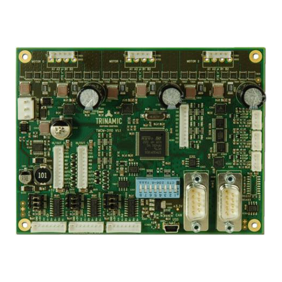
TMCM-3110 V1.1 Hardware Manual (Rev. 1.04 / 2018-11-21) Features The TMCM-3110 is a compact 3-axes stepper motor controller/driver module for 2-phase bipolar stepper motors. It is highly integrated, offers a convenient handling and can be used in many decentralized applications. The TMCM-3110 supports up to 3 bipolar stepper motors with up to 2.8A RMS coil current and supply voltages up to +48V DC nominal. - Page 4 TMCM-3110 V1.1 Hardware Manual (Rev. 1.04 / 2018-11-21) TRINAMIC – E TMCL NIQUE EATURES ASY TO SE WITH stallGuard2™ stallGuard2 is a high-precision sensorless load measurement using the back EMF on the coils. It can be used for stall detection as well as other uses at loads below those which stall the motor. The stallGuard2 measurement value changes linearly over a wide range of load, velocity, and current settings.
-
Page 5: Order Codes
A cable loom set is available for this module: Order code Description TMCM-3110-CABLE Cable loom for TMCM-3110. Contains (see chapter 3.2, also): 1x cable loom for power connector 3x cable loom for reference switch connectors 0-2 3x cable loom for motor connectors 0-2... -
Page 6: Mechanical And Electrical Interfacing
(secondary side) and mains supply earth (primary side) is not desired. In such a case, TRINAMIC recommends to use plastic (e.g. made of nylon) spacers or distance bolts. -
Page 7: Connectors
TMCM-3110 V1.1 Hardware Manual (Rev. 1.04 / 2018-11-21) 3.3 Connectors The TMCM-3110 has 16 connectors altogether. There are three separate connectors for each motor, three for corresponding reference switches, and three for encoder inputs. Further, the board has two I/O connectors, one S/D IN connector, one power connector and three connectors for communication (mini-USB, RS485, and CAN). -
Page 8: Power Connector
TMCM-3110 V1.1 Hardware Manual (Rev. 1.04 / 2018-11-21) 3.3.1 Power Connector The module offers a single power connector with the option for separate supply for driver electronics and digital controller part. A single supply voltage is sufficient. All further voltages required, e.g., for the digital components are generated on-board. -
Page 9: S/D In Connector
TMCM-3110 V1.1 Hardware Manual (Rev. 1.04 / 2018-11-21) 3.3.3 S/D IN Connector The module offers one common connector for external Step/Direction input for all three axes. This way, an external motion controller instead of the on-board one might be used together with the three on-board stepper motor driver stages. -
Page 10: I/O Connectors 0, 1
TMCM-3110 V1.1 Hardware Manual (Rev. 1.04 / 2018-11-21) 3.3.5 I/O Connectors 0, 1 The module offers two I/O connectors. The number and type of inputs, outputs and supply is the same for both connectors. Therefore, if only half of the inputs / outputs etc. is required it will be sufficient to use just one of the two connectors and reduce/simplify cabling. -
Page 11: Encoder Connector 0, 1, 2
TMCM-3110 V1.1 Hardware Manual (Rev. 1.04 / 2018-11-21) 3.3.6 Encoder Connector 0, 1, 2 For each stepper motor axis a separate encoder input connector is available. Encoders with incremental output signals – either differential (RS422 signals) or single ended (TTL or open collector signals) – with or without zero/index channel are supported. -
Page 12: Can Connector
TMCM-3110 V1.1 Hardware Manual (Rev. 1.04 / 2018-11-21) 3.3.7 CAN Connector A CAN 2.0B interface is available via a standard 9-pin male D-SUB connector. Only three pins of this connector are used. The pin assignment of these three pins is according to CiA Draft Recommendation Part 1: cabling and connector pin assignment. -
Page 13: Power Supply
TMCM-3110 V1.1 Hardware Manual (Rev. 1.04 / 2018-11-21) 3.4 Power Supply For proper operation care has to be taken with regard to power supply concept and design. The board offers around 1400uF / 63V electrolytic buffer capacitors and additionally around 28uF / 63V ceramic capacitors for supply voltage filtering. -
Page 14: Communication
For remote control and communication with a host system the TMCM-3110 provides a two wire RS485 bus interface. To select a modules’ address, the TMCM-3110 is equipped with dip switches with digits from 1 to 8. Anyhow, the switches use the binary digit system. Thus, node addresses from 1 to 255 can be set. - Page 15 TMCM-3110 V1.1 Hardware Manual (Rev. 1.04 / 2018-11-21) 4. COMMUNICATION SPEED: The maximum RS485 communication speed supported by the TMCM-3110 is 1Mbit/s. Factory default is 9600 bit/s. Please see separate TMCM-6110 TMCL firmware manual for information regarding other possible communication speeds.
-
Page 16: Can
3.5.2 CAN For remote control and communication with a host system the TMCM-3110 provides a CAN bus interface. To select a modules’ address, the TMCM-3110 is equipped with dip switches with digits from 1 to 8. Anyhow, the switches use the binary digit system. -
Page 17: Usb
(mini-USB connector). As soon as a USB-Host is connected the module will accept commands via USB. The CAN interface will be de-activated then. The TMCM-3110 supports both, USB self powered operation (when an external power is supplied via the power supply connector) and USB bus powered operation, (no external power supply via power supply connector). -
Page 18: Inputs And Outputs
See TMCL Firmware Manual chapter 5 about Axis parameters and Reference search for more details. 3.6.2 General Purpose Inputs The TMCM-3110 offers two I/O connectors with 8 inputs altogether including two dedicated analog inputs. All inputs offer the same basic input protection circuit. The dedicated analog inputs have different input voltage dividers in order to support a full scale input voltage range of 0…+10V. -
Page 19: General Purpose Outputs
The function of the inputs might differ depending on firmware version. 3.6.3 General Purpose Outputs The TMCM-3110 offers two I/O connectors with 8 outputs altogether. All 16 outputs are open-drain outputs and a freewheeling diode (to V ) is already integrated. -
Page 20: Encoder Inputs
TMCM-3110 V1.1 Hardware Manual (Rev. 1.04 / 2018-11-21) 3.6.4 Encoder Inputs The TMCM-3110 offers three connectors for incremental a/b/n encoders. Encoders with or without index/ null/zero channel are supported. Differential signals, push-pull (TTL) or open-collector are accepted. For differential signals on- board termination resistors can be activated via jumpers. -
Page 21: Step/Dir Inputs
TMCM-3110 V1.1 Hardware Manual (Rev. 1.04 / 2018-11-21) 3.6.5 Step/Dir Inputs The TMCM-3110 offers an external Step/Dir IN connector. This way, an external motion controller can be used to directly control the three on-board stepper drivers via Step/Direction instead of the on-board motion controller. -
Page 22: Motor Driver Current
SAP 6, 0, <value> // set run current SAP 7, 0, <value> // set standby current (read-out value with GAP instead of SAP. Please see separate TMCM-3110 firmware manual for further information) Motor current Resulting motor current based on motor current setting... - Page 23 TMCM-3110 V1.1 Hardware Manual (Rev. 1.04 / 2018-11-21) In addition to the settings in the table the motor current may be switched off completely (free-wheeling) using axis parameter 204 (see TMCM-3110 firmware manual). www.trinamic.com Arrow.com. Arrow.com. Arrow.com. Arrow.com. Arrow.com. Arrow.com.
-
Page 24: Onboard Leds
With standard TMCL firmware the green LED should be flashing slowly during operation and the red LED should be off. Please see separate TMCM-3110 TMCL firmware manual for additional information. If there is no valid firmware programmed into the board or during firmware update, the red and green LEDs are permanently on. -
Page 25: Reset To Factory Defaults
TMCM-3110 V1.1 Hardware Manual (Rev. 1.04 / 2018-11-21) Reset to Factory Defaults It is possible to reset the TMCM-3110 module to factory default settings without establishing a communication link. This might be helpful in case communication parameters of the preferred interface have been set to unknown values or got accidentally lost. -
Page 26: Operational Ratings
TMCM-3110 V1.1 Hardware Manual (Rev. 1.04 / 2018-11-21) Operational Ratings The operational ratings show the intended or the characteristic ranges and should be used as design values. In no case shall the maximum values be exceeded. ENERAL PERATIONAL ATINGS OF THE... - Page 27 TMCM-3110 V1.1 Hardware Manual (Rev. 1.04 / 2018-11-21) Symbol Parameter Unit Input voltage for step inputs S_0/1/2, 0 .. 24 S/D/E_0/1/2 direction inputs D_0/1/2 and enable inputs E_0/1/2 Low level voltage for step inputs S_0/1/2, S/D/E_0/1/2_L direction inputs D_0/1/2 and enable inputs...
-
Page 28: Functional Description
TMCM-3110 V1.1 Hardware Manual (Rev. 1.04 / 2018-11-21) Functional Description The TMCM-3110 is a highly integrated 3-axes controller and driver module with encoder inputs. It can be controlled via CAN, RS485 or USB serial interfaces. Communication traffic is kept low since all time critical operations, e.g. ramp calculation are performed onboard. -
Page 29: Operational Description
TMCM-3110 V1.1 Hardware Manual (Rev. 1.04 / 2018-11-21) Operational Description 9.1 Calculation: Velocity and Acceleration vs. Microstep and Fullstep Frequency The values of the parameters sent to the TMC429 do not have typical motor values like rotations per second as velocity. - Page 30 TMCM-3110 V1.1 Hardware Manual (Rev. 1.04 / 2018-11-21) XAMPLE Signal value 16 MHz velocity 1000 a_max 1000 pulse_div ramp_div usrs 1000 122070 2048 122070 1907 1000 ALCULATION OF THE NUMBER OF ROTATIONS A stepper motor has e.g. 72 fullsteps per rotation.
-
Page 31: Life Support Policy
© TRINAMIC Motion Control GmbH & Co. KG 2013 – 2018 Information given in this data sheet is believed to be accurate and reliable. However neither responsibility is assumed for the consequences of its use nor for any infringement of patents or other rights of third parties, which may result from its use. -
Page 32: Revision History
TMCM-3110 V1.1 Hardware Manual (Rev. 1.04 / 2018-11-21) 11 Revision History 11.1 Document Revision Version Date Author Description 0.90 2012-SEP-26 Preliminary version 1.00 2013-JUN-12 First complete version 1.01 2013-JUL-23 Minor changes Home switch inputs added 1.02 2014-DEC-11 Table with motor current settings added (chapter 4)
Need help?
Do you have a question about the TMCM-3110 and is the answer not in the manual?
Questions and answers