Table of Contents
Advertisement
Quick Links
Advertisement
Table of Contents

Subscribe to Our Youtube Channel
Related Manuals for Trinamic TMCM-343


Summary of Contents for Trinamic TMCM-343
- Page 1 MODULES FOR STEPPER MOTORS MODULES V 1.07 HARDWARE MANUAL TMCM- 3-axis stepper controller / driver 300mA up to 1.1A RMS nominal supply: 8V… 34V DC TMCL™ / CANopen firmware TRINAMIC Motion Control GmbH & Co. KG Hamburg, Germany www.trinamic.com...
-
Page 2: Table Of Contents
Miscellaneous connections ..........................19 7.10 Microstep resolution ............................20 Putting the TMCM-343 into operation ........................21 Migrating from the TMCM-303 to the TMCM-343 ....................22 10 TMCM-343 operational description ........................23 10.1 Calculation: Velocity and acceleration vs. microstep and fullstep frequency ......... 23 11 TMCL™... - Page 3 Figure 4.3: Pin order of the connector ........................... 8 Figure 4.4: Power supply requirements for TMCM-343 ....................9 Figure 4.5: Power supply requirements for TRINAMIC modules in a bus system .......... 10 Figure 6.1: Main parts of the TMCM-343 ........................12 Figure 6.2: Connecting the motors ..........................
-
Page 4: Life Support Policy
Specifications are subject to change without notice. Copyright © 2011, TRINAMIC Motion Control GmbH & Co. KG... -
Page 5: Features
TMCM-343 Hardware Manual (V1.07 / 2011-JUN-08) 2 Features The TMCM-343 is a compact and versatile triple axis 2-phase stepper motor controller and driver module. It provides a complete motion control solution at a very small size for embedded applications. Using the integrated additional I/Os it even can do complete system control applications. -
Page 6: Order Codes
80 x 53 x 8 mm TMCM-EVAL Evaluation baseboard 160 x 100 x 24 mm Options for TMCM-343 horizontal pin connector (standard) vertical pin connector (on request) Table 4.1: Order codes Copyright © 2011, TRINAMIC Motion Control GmbH & Co. KG... -
Page 7: Electrical And Mechanical Interfacing
39.1 50 46 36.9 R1.25 24.4 21.9 Figure 5.1: Front view of TMCM-343 (all values in mm) Horizontal Header connector connector Figure 5.2: Ordering options for the connector (all values in mm) Copyright © 2011, TRINAMIC Motion Control GmbH & Co. KG... -
Page 8: Connecting The Module
CAN - Motor1 B0 RS232 RxD Reserved in and out CAN + Motor1 B1 RS232 TxD Table 5.1: Pinout of the 68-Pin connector Figure 5.3: Pin order of the connector Copyright © 2011, TRINAMIC Motion Control GmbH & Co. KG... -
Page 9: Power Supply Requirements
TMCM-343 Hardware Manual (V1.07 / 2011-JUN-08) 5.3 Power supply requirements Two different power supplies have to be provided for the TMCM-343: +5VDC for the controller part and +7… 34VDC for the motor supply. Please connect all listed pins for the power supply inputs and ground in parallel. - Page 10 TMCM-343 CAN low CAN_ GND Figure 5.5: Power supply requirements for TRINAMIC modules in a bus system In large systems it may make sense to use an optically decoupled CAN bus for each number of nodes, e.g. for each base board with a number of TMCM-34x modules, especially when a centralized power supply is to be used.
-
Page 11: Operational Ratings
(integrated 10k pull-up to +5V for Stop) OUTx max +/- output current (CMOS +/-20 OUTI output) (sum for all outputs max. 50mA) Environment temperature at rated current °C (no cooling) Table 6.1: Operational ratings Copyright © 2011, TRINAMIC Motion Control GmbH & Co. KG... -
Page 12: Functional Description
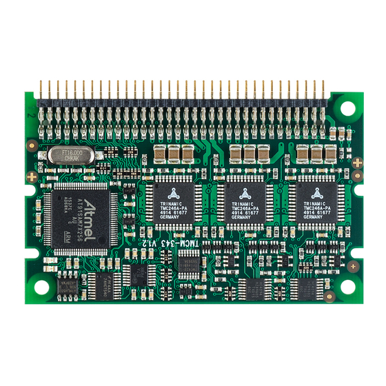
TMCM-343 Hardware Manual (V1.07 / 2011-JUN-08) 7 Functional description In Figure 7.1 the main parts of the TMCM-343 module are shown. The module mainly consists of a processor, a TMC428 motion controller, three TMC246 stepper motor drivers, the TMCL™ program memory (EEPROM) and the host interfaces RS232, RS485 and CAN. -
Page 13: Tmc428 Motion Controller
The TMCM-343 module is equipped with a circuit that extends the microstep resolution of the TMC246 chips to true 64 times microstepping. The maximum peak coil current of each stepper motor driver chip is 1500mA. -
Page 14: Host Communication
Table 7.3: Pinout for CAN connection 68 - Pin - Connector Pin 67: CAN+ + CAN+ Pin 65: CAN- - CAN- - Host TMCM-343 Pin 2 Pin 1 Figure 7.3: Connecting CAN Copyright © 2011, TRINAMIC Motion Control GmbH & Co. KG... -
Page 15: Rs232
2, 4, 6, 8, 10 Connect to ground Table 7.5: Pinout for RS485 connection The TMCM-343 module only provides a serial interface at TTL level. To use RS485 a suitable RS485 transceiver (like MAX485) has to be added by the user. Transceiver... -
Page 16: Stallguard™ - Sensorless Motor Stall Detection
7.5 stallGuard™ - sensorless motor stall detection The TMCM-343 modules are equipped with the stallGuard™ feature. The stallGuard™ feature makes it possible to detect if the mechanical load on a stepper motor is too high or if the traveler has been obstructed. -
Page 17: Stallguard™ Profiler
As it is very seldom that exactly the same result is produced when recording a profile with the same parameters a second time, always two or more profiles should be recorded and compared against each other. Copyright © 2011, TRINAMIC Motion Control GmbH & Co. KG... -
Page 18: Reference Switches
10k pull-up resistors for reference switches are included on the module. 7.6.1 Left and right limit switches The TMCM-343 can be configured so that a motor has a left and a right limit switch (Figure 7.8). The motor stops when the traveler has reached one of the limit switches. -
Page 19: One Limit Switch For Circular Systems
4, output Out_5 digital output pin 5, output Out_6 digital output pin 6, output Out_7 digital output pin 7, output Table 7.9: Additional I/O pins 7.9 Miscellaneous connections Copyright © 2011, TRINAMIC Motion Control GmbH & Co. KG... -
Page 20: Microstep Resolution
(please see the TMCM-341/342/343 TMCL™ Firmware Manual for information on this). 7.10 Microstep resolution The TMCM-343 supports a true 64 microstep resolution. To meet your needs, the microstep resolution can be set using the TMCL™ software. The default setting is 64 microsteps, which is the highest resolution. -
Page 21: Putting The Tmcm-343 Into Operation
TMCM-343 Hardware Manual (V1.07 / 2011-JUN-08) 8 Putting the TMCM-343 into operation On the basis of a small example it is shown step by step how the TMCM-343 is set into operation. Experienced users could skip this chapter and proceed to chapter 9. -
Page 22: Migrating From The Tmcm-303 To The Tmcm-343
The connector of the TMCM-343 is identical to the connector of the TMCM-303, so that a TMCM-343 can just be plugged into the slot for a TMCM-303 (it can also use the same base boards as the TMCM-303). Also the TMCL™ firmware of the TMCM-343 is highly compatible with the TMCM-303. -
Page 23: Tmcm-343 Operational Description
The change in the pulse rate per time unit (pulse frequency change per second – the acceleration a) is given by pulse ramp This results in acceleration in fullsteps of: af with af: acceleration in fullsteps usrs Copyright © 2011, TRINAMIC Motion Control GmbH & Co. KG... - Page 24 Calculation of the number of rotations: A stepper motor has e.g. 72 fullsteps per rotation. 1907 fullsteps rotation 1907 1589 fullsteps rotation Copyright © 2011, TRINAMIC Motion Control GmbH & Co. KG...
-
Page 25: Tmcl
12 CANopen The TMCM-343 module can also be used with the CANopen protocol. For this purpose, a special CANopen firmware has to be installed. To do that, download the latest version of the TMCM-343 CANopen firmware from the Trinamic website or use the version provided on the TechLib CD and install it using the firmware update function of the TMCL-IDE (Setup/Install OS). -
Page 26: Revision History
Actual version Table 13.2: Hardware revision 13.3 Firmware revision Version Comment Description 4.07 Initial release Please refer to the TMCM-341/342/343 TMCL™ Firmware Manual 4.20 Actual release Table 13.3: Firmware revision Copyright © 2011, TRINAMIC Motion Control GmbH & Co. KG... -
Page 27: References
TMCM-343 Hardware Manual (V1.07 / 2011-JUN-08) 14 References [TMCM-343] TMCM-343 Hardware Manual on www.trinamic.com [QSH-4218] QSH-4218 Manual on www.trinamic.com [TMCM-323] TMCM-323 Hardware Manual on www.trinamic.com [TMCM-EVAL] TMCM-EVAL Hardware Manual on www.trinamic.com Copyright © 2011, TRINAMIC Motion Control GmbH & Co. KG...
Need help?
Do you have a question about the TMCM-343 and is the answer not in the manual?
Questions and answers