Table of Contents
Advertisement
Quick Links
Advertisement
Table of Contents

Subscribe to Our Youtube Channel
Related Manuals for Trinamic TMCM-1310


Summary of Contents for Trinamic TMCM-1310
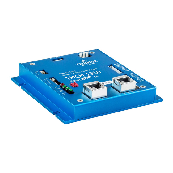
- Page 1 MODULE FOR STEPPER MOTORS MODULE Hardware Version V1.2 HARDWARE MANUAL TMCM-1310 1-Axis Stepper Closed Loop Controller / Driver 3 A RMS / 48 V ABN and SSI Encoder Input 18 GPIOs USB, EtherCAT® TRINAMIC Motion Control GmbH & Co. KG Hamburg, Germany www.trinamic.com...
-
Page 2: Table Of Contents
TMCM-1310 V1.2 Hardware Manual (Rev. 1.12 / 2013-JUL-05) Table of Contents Features ................................... 3 Order Codes ................................... 5 Mechanical and Electrical Interfacing ........................6 Dimensions ................................6 Connectors ................................7 3.2.1 Power Connector ............................8 3.2.2 Motor Connector ............................8 3.2.3... -
Page 3: Features
TMCM-1310 V1.2 Hardware Manual (Rev. 1.12 / 2013-JUL-05) 1 Features The TMCM-1310 is a single axis stepper motor controller/driver standalone board with closed loop support. For communication an USB interface and EtherCAT®* are provided. The module supports motor currents up to 3A RMS and supply voltages up to 48V nominal. The module offers inputs for one incremental a/b/n (TTL, open-collector and differential inputs) or absolute SSI encoders (selectable in software). - Page 4 EATURES LOSED The TMCM-1310 is mainly designed to run 2-phase stepper motors in closed loop mode. It offers an automatic motor load adaption in positioning mode, velocity mode, and torque mode, which is based on encoder feedback and closed loop control software for analysis, error detection and error correction.
-
Page 5: Order Codes
A cable loom set is available for this module: Order code Description TMCM-1310-CABLE Cable loom for TMCM-1310. Contains (see chapter 3.2, also): 1x cable loom for power connector 1x cable loom for reference switch connector 1x cable loom for encoder input connector... -
Page 6: Mechanical And Electrical Interfacing
TMCM-1310 V1.2 Hardware Manual (Rev. 1.12 / 2013-JUL-05) 3 Mechanical and Electrical Interfacing 3.1 Dimensions The TMCM-1310 has an overall size of 110mm x 110mm and offers four mounting holes with 4mm diameter. Maximum height (without mating connectors and cable looms) is about 26.3mm. 98.5 74.5... -
Page 7: Connectors
TMCM-1310 V1.2 Hardware Manual (Rev. 1.12 / 2013-JUL-05) 3.2 Connectors The TMCM-1310 has nine connectors altogether: one detachable connector for the motor one detachable connector for the corresponding encoder input one detachable connector for the reference switches two detachable I/O connectors one detachable power connector ©... -
Page 8: Power Connector
TMCM-1310 V1.2 Hardware Manual (Rev. 1.12 / 2013-JUL-05) 3.2.1 Power Connector The module has a single power connector with the option to have separate supplies for driver electronics and the digital controller part. A single supply voltage is sufficient. All further voltages required e.g. -
Page 9: Encoder Connector
TMCM-1310 V1.2 Hardware Manual (Rev. 1.12 / 2013-JUL-05) 3.2.3 Encoder Connector An encoder input connector (JST PH series 8pin with 2mm pitch) is available. There are possibilities for different encoder types. In addition to encoders with incremental A/B/N signals, encoders with synchronous serial interface (SSI) delivering absolute position information are supported, too. - Page 10 TMCM-1310 V1.2 Hardware Manual (Rev. 1.12 / 2013-JUL-05) 3.2.3.2 Encoders with Synchronous Serial Interface The TMCM-1310 supports encoders with synchronous serial interface (SSI) delivering absolute position information, too. In this case the encoder connector pin assignment can be switched to its alternate function as shown in Table 3.6.
-
Page 11: Reference Switch Connector
TMCM-1310 V1.2 Hardware Manual (Rev. 1.12 / 2013-JUL-05) 3.2.4 Reference Switch Connector A separate reference / limit switch input connector is available. Connector type is JST PH series 4pin with 2mm pitch. Label Direction Description Power (GND) Signal and system ground... -
Page 12: Usb Connector
TMCM-1310 V1.2 Hardware Manual (Rev. 1.12 / 2013-JUL-05) 3.2.5.2 I/O Connector 1 Label Direction Description Power (GND) Power Connected to V of Power connector. Please note: DIGITAL (supply output) max. current is 500mA (protected via on-board 500mA polyfuse) AIN4 Input Dedicated analog input, input voltage range: 0…... -
Page 13: Ethercat Link In / Link Out Connectors
TMCM-1310 V1.2 Hardware Manual (Rev. 1.12 / 2013-JUL-05) 3.2.7 EtherCAT LINK IN / LINK OUT Connectors The TMCM-1310 offers two connectors (100BASE-TX RJ-45) with standard Ethernet 100Mbit/s pin assignment for EtherCAT LINK IN (towards Master) and LINK OUT (further slaves) connection. -
Page 14: Power Supply
3.3.1 Adding an Electrolytic Capacitor TRINAMIC recommends connecting an electrolytic capacitor of significant size to the power supply lines next to the TMCM-1311. As rule of thumb, around 1000µF of capacity should be added for 1A of module power supply input current. -
Page 15: Communication
3.4 Communication 3.4.1 USB For remote control and communication with a host system the TMCM-1310 provides a USB 2.0 full-speed (12Mbit/s) interface. As soon as the USB-host is connected the module accepts commands via the USB interface. The TMCM-1310 supports USB self powered operation with external power supply via the power supply connector and USB bus powered operation without this external power supply. -
Page 16: Reference Switch Inputs
Figure 3.4 Reference switch input circuit (simplified diagram) 3.5.3 General Purpose Inputs The TMCM-1310 has two I/O connectors with 8 inputs altogether including two dedicated analog inputs. All inputs offer the same basic input protection circuit, but digital and analog inputs have different input voltages: the digital inputs have been designed for +5V and +24V signal levels. -
Page 17: General Purpose Outputs
TMCM-1310 V1.2 Hardware Manual (Rev. 1.12 / 2013-JUL-05) 3.5.4 General Purpose Outputs The TMCM-1310 offers two I/O connectors with 8 outputs altogether. All outputs are open-drain outputs and a freewheeling diode (to V ) is already integrated. Six outputs are designed for currents up to DIGTAL 100mA and two outputs offer more powerful MOSFET driver transistors supporting currents up to 1A. -
Page 18: On-Board Leds
TMCM-1310 V1.2 Hardware Manual (Rev. 1.12 / 2013-JUL-05) 4 On-Board LEDs The TMCM-1310 offers four LEDs for indicating EtherCAT communication and board status. The three green LEDs are related to the EtherCAT interface and indicate EtherCAT LINK IN and LINK OUT activity plus the status of the EtherCAT state machine. -
Page 19: Operational Ratings
TMCM-1310 V1.2 Hardware Manual (Rev. 1.12 / 2013-JUL-05) 5 Operational Ratings The operational ratings show the intended or the characteristic ranges and should be used as design values. In no case shall the maximum values be exceeded. Symbol Parameter Unit Power supply voltage for driver 12..24..48... -
Page 20: Functional Description
TMCM-1310 V1.2 Hardware Manual (Rev. 1.12 / 2013-JUL-05) 6 Functional Description The TMCM-1310 is a highly integrated single axis closed loop controller / driver module which can be controlled via USB or EtherCAT. Communication traffic is kept low since all time critical operations (e.g. -
Page 21: Life Support Policy
TMCM-1310 V1.2 Hardware Manual (Rev. 1.12 / 2013-JUL-05) 7 Life Support Policy TRINAMIC Motion Control GmbH & Co. KG does not authorize or warrant any of its products for use in life support systems, without the specific written consent of TRINAMIC Motion Control GmbH &... -
Page 22: Revision History
TMCM-1310 V1.2 Hardware Manual (Rev. 1.12 / 2013-JUL-05) 8 Revision History 8.1 Document Revision Version Date Author Description 0.90 2012-OCT-25 Preliminary version 1.00 2012-DEC-06 First complete version 1.10 2013-MAY-23 Adapted to latest hardware version V1.2 1.11 2013-JUL-03 Changes related to the design 1.12...
Need help?
Do you have a question about the TMCM-1310 and is the answer not in the manual?
Questions and answers