Table of Contents
Advertisement
Quick Links
Advertisement
Table of Contents

Related Manuals for Trinamic TMCM-6110


Summary of Contents for Trinamic TMCM-6110
- Page 1 MODULE FOR STEPPER MOTORS MODULE Firmware Version V1.31 TMCL™ FIRMWARE MANUAL TMCM-6110 6 Axes Stepper Controller / Driver 1.1A RMS / 24V DC USB, CAN, RS485 [or RS232] TRINAMIC Motion Control GmbH & Co. KG Hamburg, Germany www.trinamic.com...
-
Page 2: Table Of Contents
TMCM-6110 TMCL Firmware V1.31 Manual (Rev. 1.09 / 2015-FEB-24) Table of Contents Features ................................... 4 Overview ..................................5 Putting the Module into Operation ........................6 Basic Set-up ................................6 3.1.1 Connecting the Module ..........................6 3.1.2 Start the TMCL-IDE Software Development Environment ............... 11 3.1.3... -
Page 3: Tmcm-6110 Tmcl Firmware V1.31 Manual (Rev. 1.09 / 2015-Feb-24)
TMCM-6110 TMCL Firmware V1.31 Manual (Rev. 1.09 / 2015-FEB-24) 4.6.35 RETI (return from interrupt) ........................66 4.6.36 Customer Specific TMCL Command Extension (user function) ............67 4.6.37 Request Target Position Reached Event ....................68 4.6.38 BIN (return to binary mode) ........................69 4.6.39 TMCL Control Functions .......................... -
Page 4: Features
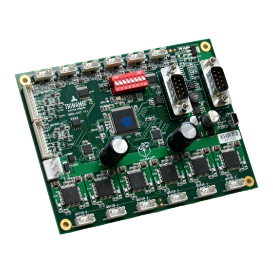
TMCM-6110 TMCL Firmware V1.31 Manual (Rev. 1.09 / 2015-FEB-24) 1 Features The TMCM-6110 is a compact 6-axes stepper motor controller/driver standalone board. It supports up to 6 bipolar stepper motors with up to 1.1A RMS coil current. There are separate motor and reference/end switch connectors for each motor. -
Page 5: Overview
TMCM-6110 TMCL Firmware V1.31 Manual (Rev. 1.09 / 2015-FEB-24) 2 Overview The software running on the microprocessor of the TMCM-6110 consists of two parts, a boot loader and the firmware itself. Whereas the boot loader is installed during production and testing at TRINAMIC and remains untouched throughout the whole lifetime, the firmware can be updated by the user. -
Page 6: Putting The Module Into Operation
THINGS YOU NEED TMCM-6110 with up to six appropriate motors (e.g. QSH4218) Interface (RS485, CAN or USB) suitable to your TMCM-6110 module with cables Nominal supply voltage +24V DC (+9… +28V DC) for your module TMCL-IDE program (can be downloaded free of charge from www.trinamic.com) - Page 7 Description RS485- Bi-directional Differential RS485 bus signal (inverting) Power (GND) Signal and system ground RS485+ Bi-directional Differential RS485 bus signal (non-inverting) RS485 as field bus interface normally requires an adapter. TRINAMIC offers the USB-2-485 converter between USB and RS485. www.trinamic.com...
- Page 8 Connect the USB interface with the appropriate connector (see Figure 3.1). To make use of the USB interface, a device driver has to be installed first. When the TMCM-6110 module is connected to the USB interface of a PC for the first time, you will be prompted for a driver by the operating system. The tmcm- 6110.inf file is available on www.trinamic.com.
- Page 9 TMCM-6110 TMCL Firmware V1.31 Manual (Rev. 1.09 / 2015-FEB-24) 3.1.1.3 Motor The TMCM-6110 controls up to six 2-phase stepper motors. Connect one coil of each motor to the terminals marked A0 and A1 and the other coil to the connectors marked B0 and B1.
- Page 10 TMCM-6110 TMCL Firmware V1.31 Manual (Rev. 1.09 / 2015-FEB-24) 3.1.1.5 I/Os Connect inputs and outputs with the appropriate connectors (see Figure 3.1), if you want to use them. Label Connector type Mating connector type Connector housing CVIlux: CI010105000-A Contacts CVIlux: CI01T011PE0-A...
-
Page 11: Start The Tmcl-Ide Software Development Environment
TMCM-6110 TMCL Firmware V1.31 Manual (Rev. 1.09 / 2015-FEB-24) 3.1.2 Start the TMCL-IDE Software Development Environment The TMCL-IDE is available on www.trinamic.com. TMCL-IDE: NSTALLING THE Make sure the COM port you intend to use is not blocked by another program. -
Page 12: Using Tmcl Direct Mode
Start TMCL Direct Mode. Direct Mode If the communication is established the TMCM-6110 is automatically detected. If the module is not detected, please check cables, interface, power supply, COM port, and baud rate. Issue a command by choosing Instruction, Type (if necessary), Motor, and Value and click Execute to send it to the module. -
Page 13: Important Motor Settings
TMCM-6110 TMCL Firmware V1.31 Manual (Rev. 1.09 / 2015-FEB-24) 3.1.4 Important Motor Settings There are some axis parameters which have to be adjusted right in the beginning after installing your module. Please set the upper limiting values for the speed (axis parameter 4), the acceleration (axis parameter 5), and the current (axis parameter 6). -
Page 14: Tmcl Program Example
Download Click on Icon Assemble to convert the TMCL into machine code. Then download the program to the TMCM-6110 module via the icon Download. Press icon Run. The desired program will be executed. Click Stop button to stop the program. -
Page 15: Tmcl And Tmcl-Ide
That is, a host computer (e.g. PC/PLC) acting as the interface bus master will send a command to the TMCM-6110. The TMCL interpreter on the module will then interpret this command, do the initialization of the motion controller, read inputs and write outputs or whatever is necessary according to the specified command. -
Page 16: Reply Format
TMCM-6110 TMCL Firmware V1.31 Manual (Rev. 1.09 / 2015-FEB-24) HECKSUM CALCULATION As mentioned above, the checksum is calculated by adding up all bytes (including the module address byte) using 8-bit addition. Here are two examples to show how to do this: in C: unsigned char i, Checksum;... -
Page 17: Tmcl Command Overview
TMCM-6110 TMCL Firmware V1.31 Manual (Rev. 1.09 / 2015-FEB-24) 4.4 TMCL Command Overview In this section a short overview of the TMCL commands is given. 4.4.1 TMCL Commands Command Number Parameter Description <motor number>, <velocity> Rotate right with specified velocity <motor number>, <velocity>... -
Page 18: Commands Listed According To Subject Area
TMCM-6110 TMCL Firmware V1.31 Manual (Rev. 1.09 / 2015-FEB-24) 4.4.2 Commands Listed According to Subject Area 4.4.2.1 Motion Commands These commands control the motion of the motor. They are the most important commands and can be used in direct mode or in standalone mode. - Page 19 TMCM-6110 TMCL Firmware V1.31 Manual (Rev. 1.09 / 2015-FEB-24) 4.4.2.5 Calculation Commands These commands are intended to be used for calculations within TMCL applications. Although they could also be used in direct mode it does not make much sense to do so.
- Page 20 TMCM-6110 TMCL Firmware V1.31 Manual (Rev. 1.09 / 2015-FEB-24) 4.4.2.6.3 Interrupt Vectors: The following table shows all interrupt vectors that can be used. Interrupt number Interrupt type Timer 0 Timer 1 Timer 2 Target position reached axis 0 Target position reached axis 1...
- Page 21 The beginning of the program above then looks like the following: #include Interrupts.inc VECT TI_TIMER0, Timer0Irq SGP TI_TIMER0, 3, 1000 EI TI_TIMER0 EI TI_GLOBAL Please also take a look at the other example programs (see www.trinamic.com). 4.4.2.7 ASCII Commands Mnemonic Command number Meaning Enter ASCII mode Quit ASCII mode and return to binary mode.
-
Page 22: The Ascii Interface
TMCM-6110 TMCL Firmware V1.31 Manual (Rev. 1.09 / 2015-FEB-24) 4.5 The ASCII Interface There is also an ASCII interface that can be used to communicate with the module and to send some commands as text strings. ROCEED AS FOLLOWS The ASCII command line interface is entered by sending the binary command 139 (enter ASCII mode). -
Page 23: Configuring The Ascii Interface
TMCM-6110 TMCL Firmware V1.31 Manual (Rev. 1.09 / 2015-FEB-24) 4.5.4 Configuring the ASCII Interface The module can be configured so that it starts up either in binary mode or in ASCII mode. Global parameter 67 is used for this purpose (please see also chapter 6.1). -
Page 24: Commands
TMCM-6110 TMCL Firmware V1.31 Manual (Rev. 1.09 / 2015-FEB-24) 4.6 Commands The module specific commands are explained in more detail on the following pages. They are listed according to their command number. 4.6.1 ROR (rotate right) The motor will be instructed to rotate with a specified velocity in right direction (increasing the position counter). -
Page 25: Rol (Rotate Left)
TMCM-6110 TMCL Firmware V1.31 Manual (Rev. 1.09 / 2015-FEB-24) 4.6.2 ROL (rotate left) The motor will be instructed to rotate with a specified velocity (opposite direction compared to ROR, decreasing the position counter). Internal function: first, velocity mode is selected. Then, the velocity value is transferred to axis parameter #2 (target velocity). -
Page 26: Mst (Motor Stop)
TMCM-6110 TMCL Firmware V1.31 Manual (Rev. 1.09 / 2015-FEB-24) 4.6.3 MST (motor stop) The motor will be instructed to stop. Internal function: the axis parameter target velocity is set to zero. Related commands: ROL, ROR, SAP, GAP Mnemonic: MST <motor>... -
Page 27: Mvp (Move To Position)
TMCM-6110 TMCL Firmware V1.31 Manual (Rev. 1.09 / 2015-FEB-24) 4.6.4 MVP (move to position) The motor will be instructed to move to a specified relative or absolute position or a pre-programmed coordinate. It will use the acceleration/deceleration ramp and the positioning speed programmed into the unit. - Page 28 TMCM-6110 TMCL Firmware V1.31 Manual (Rev. 1.09 / 2015-FEB-24) Versatile options for the MVP COORD command: Moving only one motor: Set the <motor> parameter to the motor number (0…2). Moving multiple motors without interpolation: Set bit 7 of the <motor> parameter. Now the bits 0…2 of the <motor>...
-
Page 29: Sap (Set Axis Parameter)
TMCM-6110 TMCL Firmware V1.31 Manual (Rev. 1.09 / 2015-FEB-24) 4.6.5 SAP (set axis parameter) With this command most of the motion control parameters can be specified. The settings will be stored in SRAM and therefore are volatile. That is, information will be lost after power off. -
Page 30: Gap (Get Axis Parameter)
4.6.6 GAP (get axis parameter) Most parameters of the TMCM-6110 can be adjusted individually for the axis. With this parameter they can be read out. In standalone mode the requested value is also transferred to the accumulator register for further processing purposes (such as conditioned jumps). In direct mode the value read is only output in the value field of the reply (without affecting the accumulator). -
Page 31: Stap (Store Axis Parameter)
TMCM-6110 TMCL Firmware V1.31 Manual (Rev. 1.09 / 2015-FEB-24) 4.6.7 STAP (store axis parameter) An axis parameter previously set with a Set Axis Parameter command (SAP) will be stored permanent. Most parameters are automatically restored after power up. For a table with parameters and values which can be used together with this command please refer to chapter 5. -
Page 32: Rsap (Restore Axis Parameter)
TMCM-6110 TMCL Firmware V1.31 Manual (Rev. 1.09 / 2015-FEB-24) 4.6.8 RSAP (restore axis parameter) For all configuration-related axis parameters non-volatile memory locations are provided. By default, most parameters are automatically restored after power up. A single parameter that has been changed before can be reset by this instruction also. -
Page 33: Sgp (Set Global Parameter)
TMCM-6110 TMCL Firmware V1.31 Manual (Rev. 1.09 / 2015-FEB-24) 4.6.9 SGP (set global parameter) With this command most of the module specific parameters not directly related to motion control can be specified and the TMCL user variables can be changed. Global parameters are related to the host interface, peripherals or application specific variables. -
Page 34: Ggp (Get Global Parameter)
TMCM-6110 TMCL Firmware V1.31 Manual (Rev. 1.09 / 2015-FEB-24) 4.6.10 GGP (get global parameter) All global parameters can be read with this function. Global parameters are related to the host interface, peripherals or application specific variables. The different groups of these parameters are organized in banks to allow a larger total number for future products. -
Page 35: Stgp (Store Global Parameter)
TMCM-6110 TMCL Firmware V1.31 Manual (Rev. 1.09 / 2015-FEB-24) 4.6.11 STGP (store global parameter) This command is used to store TMCL user variables permanently in the EEPROM of the module. Some global parameters are located in RAM memory, so without storing modifications are lost at power down. -
Page 36: Rsgp (Restore Global Parameter)
TMCM-6110 TMCL Firmware V1.31 Manual (Rev. 1.09 / 2015-FEB-24) 4.6.12 RSGP (restore global parameter) With this command the contents of a TMCL user variable can be restored from the EEPROM. For all configuration-related axis parameters, non-volatile memory locations are provided. By default, most parameters are automatically restored after power up. -
Page 37: Rfs (Reference Search)
TMCM-6110 TMCL Firmware V1.31 Manual (Rev. 1.09 / 2015-FEB-24) 4.6.13 RFS (reference search) The TMCM-6110 has a built-in reference search algorithm which can be used. The reference search algorithm provides switching point calibration and supports up-to three switches. The status of the reference search can also be queried to see if it has already been finished. -
Page 38: Sio (Set Input / Output)
TMCM-6110 TMCL Firmware V1.31 Manual (Rev. 1.09 / 2015-FEB-24) 4.6.14 SIO (set input / output) This command can be used as follows: SIO sets the status of the general digital output either to low (0) or to high (1). Bank 2 is used for this purpose. - Page 39 TMCM-6110 TMCL Firmware V1.31 Manual (Rev. 1.09 / 2015-FEB-24) CONNECTOR Connector 0 Connector 1 Direction Description Power (GND) Power Connected to V of power connector DIGITAL DIGITAL DIGITAL (supply output) Dedicated analog input, AIN_0 AIN_4 Input input voltage range: 0… +10V, resolution: 12bit (0…...
- Page 40 TMCM-6110 TMCL Firmware V1.31 Manual (Rev. 1.09 / 2015-FEB-24) WITCHING THE PULL UP RESISTORS OF THE REFERENCE SWITCH INPUTS SIO can be used to switch the pull-up resistors for all reference switch inputs on and off. Bank 0 is used for this purpose.
-
Page 41: Gio (Get Input /Output)
TMCM-6110 TMCL Firmware V1.31 Manual (Rev. 1.09 / 2015-FEB-24) 4.6.15 GIO (get input /output) With this command the status of the two available general purpose inputs of the module can be read out. The function reads a digital or analogue input port. Digital lines will read 0 and 1, while the ADC channels deliver their 12 bit result in the range of 0…... - Page 42 TMCM-6110 TMCL Firmware V1.31 Manual (Rev. 1.09 / 2015-FEB-24) Reference switch connectors Axis 0 Axis 1 Axis 2 Axis 3 Axis 4 Axis5 I/O connector 0 I/O connector 1 Figure 4.2 Connectors of TMCM-6110 CONNECTOR Connector 0 Connector 1 Direction...
- Page 43 TMCM-6110 TMCL Firmware V1.31 Manual (Rev. 1.09 / 2015-FEB-24) EADING ALL DIGITAL INPUTS WITH ONE COMMAND Set the type parameter to 255 and the bank parameter to 0. In this case the status of all digital input lines will be read to the lower eight bits of the accumulator.
-
Page 44: Calc (Calculate)
TMCM-6110 TMCL Firmware V1.31 Manual (Rev. 1.09 / 2015-FEB-24) 4.6.16 CALC (calculate) A value in the accumulator variable, previously read by a function such as GAP (get axis parameter) can be modified with this instruction. Nine different arithmetic functions can be chosen and one constant operand value must be specified. -
Page 45: Comp (Compare)
TMCM-6110 TMCL Firmware V1.31 Manual (Rev. 1.09 / 2015-FEB-24) 4.6.17 COMP (compare) The specified number is compared to the value in the accumulator register. The result of the comparison can for example be used by the conditional jump (JC) instruction. -
Page 46: Jc (Jump Conditional)
TMCM-6110 TMCL Firmware V1.31 Manual (Rev. 1.09 / 2015-FEB-24) 4.6.18 JC (jump conditional) The JC instruction enables a conditional jump to a fixed address in the TMCL program memory, if the specified condition is met. The conditions refer to the result of a preceding comparison. Please refer to COMP instruction for examples. -
Page 47: Ja (Jump Always)
TMCM-6110 TMCL Firmware V1.31 Manual (Rev. 1.09 / 2015-FEB-24) 4.6.19 JA (jump always) Jump to a fixed address in the TMCL program memory. This command is intended for standalone operation only. Internal function: the TMCL program counter is set to the passed value. -
Page 48: Csub (Call Subroutine)
TMCM-6110 TMCL Firmware V1.31 Manual (Rev. 1.09 / 2015-FEB-24) 4.6.20 CSUB (call subroutine) This function calls a subroutine in the TMCL program memory. This command is intended for standalone operation only. Internal function: the actual TMCL program counter value is saved to an internal stack, afterwards overwritten with the passed value. -
Page 49: Rsub (Return From Subroutine)
TMCM-6110 TMCL Firmware V1.31 Manual (Rev. 1.09 / 2015-FEB-24) 4.6.21 RSUB (return from subroutine) Return from a subroutine to the command after the CSUB command. This command is intended for use in standalone mode only. Internal function: the TMCL program counter is set to the last value of the stack. The command will be ignored if the stack is empty. -
Page 50: Wait (Wait For An Event To Occur)
TMCM-6110 TMCL Firmware V1.31 Manual (Rev. 1.09 / 2015-FEB-24) 4.6.22 WAIT (wait for an event to occur) This instruction interrupts the execution of the TMCL program until the specified condition is met. This command is intended for standalone operation only. -
Page 51: Stop (Stop Tmcl Program Execution)
TMCM-6110 TMCL Firmware V1.31 Manual (Rev. 1.09 / 2015-FEB-24) 4.6.23 STOP (stop TMCL program execution) This function stops executing a TMCL program. The host address and the reply are only used to transfer the instruction to the TMCL program memory. -
Page 52: Sco (Set Coordinate)
TMCM-6110 TMCL Firmware V1.31 Manual (Rev. 1.09 / 2015-FEB-24) 4.6.24 SCO (set coordinate) Up to 20 position values (coordinates) can be stored for every axis for use with the MVP COORD command. This command sets a coordinate to a specified value. Depending on the global parameter 84, the coordinates are only stored in RAM or also stored in the EEPROM and copied back on startup (with the default setting the coordinates are stored in RAM only). -
Page 53: Gco (Get Coordinate)
TMCM-6110 TMCL Firmware V1.31 Manual (Rev. 1.09 / 2015-FEB-24) 4.6.25 GCO (get coordinate) This command makes possible to read out a previously stored coordinate. In standalone mode the requested value is copied to the accumulator register for further processing purposes such as conditioned jumps. -
Page 54: Cco (Capture Coordinate)
TMCM-6110 TMCL Firmware V1.31 Manual (Rev. 1.09 / 2015-FEB-24) 4.6.26 CCO (capture coordinate) The actual position of the axis is copied to the selected coordinate variable. Depending on the global parameter 84, the coordinates are only stored in RAM or also stored in the EEPROM and copied back on startup (with the default setting the coordinates are stored in RAM only). -
Page 55: Aco (Accu To Coordinate)
TMCM-6110 TMCL Firmware V1.31 Manual (Rev. 1.09 / 2015-FEB-24) 4.6.27 ACO (accu to coordinate) With the ACO command the actual value of the accumulator is copied to a selected coordinate of the motor. Depending on the global parameter 84, the coordinates are only stored in RAM or also stored in the EEPROM and copied back on startup (with the default setting the coordinates are stored in RAM only). -
Page 56: Calcx (Calculate Using The X Register)
TMCM-6110 TMCL Firmware V1.31 Manual (Rev. 1.09 / 2015-FEB-24) 4.6.28 CALCX (calculate using the X register) This instruction is very similar to CALC, but the second operand comes from the X register. The X register can be loaded with the LOAD or the SWAP type of this instruction. The result is written back to the accumulator for further processing like comparisons or data transfer. -
Page 57: Aap (Accumulator To Axis Parameter)
TMCM-6110 TMCL Firmware V1.31 Manual (Rev. 1.09 / 2015-FEB-24) 4.6.29 AAP (accumulator to axis parameter) The content of the accumulator register is transferred to the specified axis parameter. For practical usage, the accumulator has to be loaded e.g. by a preceding GAP instruction. The accumulator may have been modified by the CALC or CALCX (calculate) instruction. -
Page 58: Agp (Accumulator To Global Parameter)
TMCM-6110 TMCL Firmware V1.31 Manual (Rev. 1.09 / 2015-FEB-24) 4.6.30 AGP (accumulator to global parameter) The content of the accumulator register is transferred to the specified global parameter. For practical usage, the accumulator has to be loaded e.g. by a preceding GAP instruction. The accumulator may have been modified by the CALC or CALCX (calculate) instruction. -
Page 59: Cle (Clear Error Flags)
TMCM-6110 TMCL Firmware V1.31 Manual (Rev. 1.09 / 2015-FEB-24) 4.6.31 CLE (clear error flags) This command clears the internal error flags. This command is intended for use in standalone mode only and must not be used in direct mode. <... -
Page 60: Vect (Set Interrupt Vector)
TMCM-6110 TMCL Firmware V1.31 Manual (Rev. 1.09 / 2015-FEB-24) 4.6.32 VECT (set interrupt vector) The VECT command defines an interrupt vector. It needs an interrupt number and a label as parameter (like in JA, JC and CSUB commands). This label must be the entry point of the interrupt handling routine. - Page 61 TMCM-6110 TMCL Firmware V1.31 Manual (Rev. 1.09 / 2015-FEB-24) Example: Define interrupt vector at target position 500 VECT 3, 500 Binary format of VECT: Byte Index Function Target- Type Motor/ Operand Operand Operand Operand Instruction address Number Bank Byte3 Byte2...
-
Page 62: Ei (Enable Interrupt)
TMCM-6110 TMCL Firmware V1.31 Manual (Rev. 1.09 / 2015-FEB-24) 4.6.33 EI (enable interrupt) The EI command enables an interrupt. It needs the interrupt number as parameter. Interrupt number 255 globally enables interrupts. Related command: DI, VECT, RETI Mnemonic: EI <interrupt number>... - Page 63 TMCM-6110 TMCL Firmware V1.31 Manual (Rev. 1.09 / 2015-FEB-24) Examples: Enable interrupts globally EI, 255 Binary format of EI: Byte Index Function Target- Type Motor/ Operand Operand Operand Operand Instruction address Number Bank Byte3 Byte2 Byte1 Byte0 Value (hex) Enable interrupt when target position reached...
-
Page 64: Di (Disable Interrupt)
TMCM-6110 TMCL Firmware V1.31 Manual (Rev. 1.09 / 2015-FEB-24) 4.6.34 DI (disable interrupt) The DI command disables an interrupt. It needs the interrupt number as parameter. Interrupt number 255 globally disables interrupts. Related command: EI, VECT, RETI Mnemonic: DI <interrupt number>... - Page 65 TMCM-6110 TMCL Firmware V1.31 Manual (Rev. 1.09 / 2015-FEB-24) Examples: Disable interrupts globally DI, 255 Binary format of DI: Byte Index Function Target- Type Motor/ Operand Operand Operand Operand Instruction address Number Bank Byte3 Byte2 Byte1 Byte0 Value (hex) Disable interrupt when target position reached...
-
Page 66: Reti (Return From Interrupt)
TMCM-6110 TMCL Firmware V1.31 Manual (Rev. 1.09 / 2015-FEB-24) 4.6.35 RETI (return from interrupt) This command terminates the interrupt handling routine, and the normal program execution continues. At the end of an interrupt handling routine the RETI command must be executed. -
Page 67: Customer Specific Tmcl Command Extension (User Function)
4.6.36 Customer Specific TMCL Command Extension (user function) The user definable functions UF0… UF7 are predefined functions without topic for user specific purposes. A user function (UF) command uses three parameters. Please contact TRINAMIC for a customer specific programming. Internal function: Call user specific functions implemented in C by TRINAMIC. -
Page 68: Request Target Position Reached Event
TMCM-6110 TMCL Firmware V1.31 Manual (Rev. 1.09 / 2015-FEB-24) 4.6.37 Request Target Position Reached Event This command is the only exception to the TMCL protocol, as it sends two replies: One immediately after the command has been executed (like all other commands also), and one additional reply that will be sent when the motor has reached its target position. -
Page 69: Bin (Return To Binary Mode)
TMCM-6110 TMCL Firmware V1.31 Manual (Rev. 1.09 / 2015-FEB-24) 4.6.38 BIN (return to binary mode) This command can only be used in ASCII mode. It quits the ASCII mode and returns to binary mode. Related Commands: none Mnemonic: BIN Binary representation: This command does not have a binary representation as it can only be used in ASCII mode. -
Page 70: Tmcl Control Functions
TMCM-6110 TMCL Firmware V1.31 Manual (Rev. 1.09 / 2015-FEB-24) 4.6.39 TMCL Control Functions There are several TMCL control functions, but for the user are only 136 and 137 interesting. Other control functions can be used with axis parameters. Instruction number... -
Page 71: Axis Parameters
TMCM-6110 TMCL Firmware V1.31 Manual (Rev. 1.09 / 2015-FEB-24) 5 Axis Parameters The following sections describe all axis parameters that can be used with the SAP, GAP, AAP, STAP, and RSAP commands. EANING OF THE LETTERS IN COLUMN CCESS Access... - Page 72 TMCM-6110 TMCL Firmware V1.31 Manual (Rev. 1.09 / 2015-FEB-24) Number Axis Parameter Description Range [Unit] Acc. Absolute max. The maximum value is 255. This value means 0… 255 current 100% of the maximum current of the module. (CS / Current The current adjustment is within the range 0…...
- Page 73 TMCM-6110 TMCL Firmware V1.31 Manual (Rev. 1.09 / 2015-FEB-24) Number Axis Parameter Description Range [Unit] Acc. Microstep full step 0… 8 resolution half step 4 microsteps 8 microsteps 16 microsteps 32 microsteps 64 microsteps 128 microsteps 256 microsteps Reference switch For three-switch mode: a position range, 0…...
- Page 74 TMCM-6110 TMCL Firmware V1.31 Manual (Rev. 1.09 / 2015-FEB-24) Number Axis Parameter Description Range [Unit] Acc. Chopper Hysteresis start setting. Please remark, that 0… 8 hysteresis start this value is an offset to the hysteresis end value. Chopper off time The off time setting controls the minimum 0 / 2…...
- Page 75 TMCM-6110 TMCL Firmware V1.31 Manual (Rev. 1.09 / 2015-FEB-24) Number Axis Parameter Description Range [Unit] Acc. stallGuard2 filter Enables stallGuard2 filter more enable precision of the measurement. If set, reduces measurement frequency measurement per four fullsteps. In most cases it is expedient to set the filtered mode before using coolStep.
- Page 76 TMCM-6110 TMCL Firmware V1.31 Manual (Rev. 1.09 / 2015-FEB-24) Number Axis Parameter Description Range [Unit] Acc. smartEnergy Sets the motor current which is used below 0… 255 slow run current the threshold speed. Random chopper Enable randomizing the slow decay phase...
- Page 77 TMCM-6110 TMCL Firmware V1.31 Manual (Rev. 1.09 / 2015-FEB-24) Number Axis Parameter Description Range [Unit] Acc. TMC260 driver Bit 0 stallGuard2 status error flags (1: threshold reached) Bit 1 Overtemperature (1: driver is shut down due to overtemperature) Bit 2...
-
Page 78: Stallguard2 Related Parameters
TMCM-6110 TMCL Firmware V1.31 Manual (Rev. 1.09 / 2015-FEB-24) 5.1 stallGuard2 Related Parameters The module is equipped with TMC260 motor driver chip. The TMC260 features load measurement that can be used for stall detection. stallGuard2 delivers a sensorless load measurement of the motor as well as a stall detection signal. - Page 79 TMCM-6110 TMCL Firmware V1.31 Manual (Rev. 1.09 / 2015-FEB-24) Number Axis Parameter Description stallGuard2 This signed value controls stallGuard2 threshold level for stall output and sets threshold the optimum measurement range for readout. A lower value gives a higher sensitivity. Zero is the starting value. A higher value makes stallGuard2 less sensitive and requires more torque to indicate a stall.
-
Page 80: Coolstep Related Parameters
TMCM-6110 TMCL Firmware V1.31 Manual (Rev. 1.09 / 2015-FEB-24) 5.2 coolStep Related Parameters The figure below gives an overview of the coolStep related parameters. Please have in mind that the figure shows only one example for a drive. There are parameters which concern the configuration of the current. - Page 81 TMCM-6110 TMCL Firmware V1.31 Manual (Rev. 1.09 / 2015-FEB-24) ARAMETERS NEEDED FOR ADJUSTING THE COOL TEP FEATURE Number Axis parameter Description The maximum value is 255. This value means 100% of the maximum current of the module. The current adjustment is within the range 0…...
-
Page 82: Reference Search
TMCM-6110 TMCL Firmware V1.31 Manual (Rev. 1.09 / 2015-FEB-24) 5.3 Reference Search The built-in reference search feature (instruction RFS, no. 13) offers switching point calibration and supports up-to two end / stop / limit switches and one home switch. Depending on the selected reference search mode (see table below), one of the limit switches or the home switch might be used as reference switch and the end / limit switches are either respected or ignored during the reference search. -
Page 83: Reference Search Modes (Axis Parameter 193)
TMCM-6110 TMCL Firmware V1.31 Manual (Rev. 1.09 / 2015-FEB-24) XIS PARAMETERS RELATED TO REFERENCE SEARCH Number Axis Parameter Description Reference switch The logical state of the home switch. status Right limit The logical state of the right limit switch. switch status... - Page 84 TMCM-6110 TMCL Firmware V1.31 Manual (Rev. 1.09 / 2015-FEB-24) SAP 193, 0, 2 Search right stop switch, then search left stop switch : reference search speed (axis parameter 194) : reference switch speed (axis parameter 195) start stop left limit / end / stop switch right limit / end / stop switch Figure 5.3: Search right stop switch, then search left stop switch...
- Page 85 TMCM-6110 TMCL Firmware V1.31 Manual (Rev. 1.09 / 2015-FEB-24) SAP 193, 0, 6 Search home switch in positive direction, reverse direction in case right stop switch is hit : reference search speed (axis parameter 194) : reference switch speed (axis parameter 195)
-
Page 86: Grouping Motors
Motors that have the same group index belong to the same group All motors that belong to one group must be controlled by the same TMCM-6110 module. This method allows a great flexibility for grouping motors together. For example, it is possible to form two groups of three motors, or three groups of two motors, or one group of four motors or any other combinations. -
Page 87: Calculation: Velocity And Acceleration Vs. Microstep- And Fullstep-Frequency
TMCM-6110 TMCL Firmware V1.31 Manual (Rev. 1.09 / 2015-FEB-24) 5.5 Calculation: Velocity and Acceleration vs. Microstep- and Fullstep-Frequency The values of the axis parameters, sent to the TMC429 do not have typical motor values, like rotations per second as velocity. But these values can be calculated from the TMC429 parameters, as shown in this document. -
Page 88: Fullstep Frequency
TMCM-6110 TMCL Firmware V1.31 Manual (Rev. 1.09 / 2015-FEB-24) 5.5.2 Fullstep Frequency To calculate the fullstep frequency from the microstep frequency, the microstep frequency must be divided by the number of microsteps per fullstep. fsf: fullstep-frequency The change in the pulse rate per time unit (... -
Page 89: Global Parameters
TMCL-IDE and serve for loading microstep and driver tables. Normally these parameters remain untouched. If you want to use them for loading your specific values with your PC software please contact TRINAMIC and ask how to do this. Otherwise you might cause damage on the motor driver! - Page 90 TMCM-6110 TMCL Firmware V1.31 Manual (Rev. 1.09 / 2015-FEB-24) Number Global parameter Description Range Acc. EEPROM magic Setting this parameter to a different value as $E4 0… 255 will cause re-initialization of the axis and global parameters (to factory defaults) after the next power up.
- Page 91 TMCM-6110 TMCL Firmware V1.31 Manual (Rev. 1.09 / 2015-FEB-24) Number Global parameter Description Range Acc. End switch polarity 0 - normal polarity motor axis 0..5 0,1,2,3 1 - reverse polarity motor axis 0..2, normal polarity motor axis 3..5 2 - normal polarity motor axis 0..2, reverse polarity motor axis 3..5...
-
Page 92: Bank 1
TMCM-6110 TMCL Firmware V1.31 Manual (Rev. 1.09 / 2015-FEB-24) to receive too late. To overcome this problem, set the telegram pause time (global parameter #75) of the module to 15 (or more if needed) by issuing an SGP 75, 0, 15 command in direct mode. The parameter will automatically be stored in the configuration EEPROM. -
Page 93: Bank 3
TMCM-6110 TMCL Firmware V1.31 Manual (Rev. 1.09 / 2015-FEB-24) 6.4 Bank 3 Bank 3 contains interrupt parameters. Some interrupts need configuration (e.g. the timer interval of a timer interrupt). This can be done using the SGP commands with parameter bank 3 (SGP <type>, 3, <value>). The priority of an interrupt depends on its number. -
Page 94: Tmcl Programming Techniques And Structure
TMCM-6110 TMCL Firmware V1.31 Manual (Rev. 1.09 / 2015-FEB-24) 7 TMCL Programming Techniques and Structure 7.1 Initialization The first task in a TMCL program (like in other programs also) is to initialize all parameters where different values than the default values are necessary. For this purpose, SAP and SGP commands are used. -
Page 95: Using Variables
TMCM-6110 TMCL Firmware V1.31 Manual (Rev. 1.09 / 2015-FEB-24) 7.4 Using Variables User variables can be used if variables are needed in your program. They can store temporary values. The commands SGP, GGP and AGP are used to work with user variables: is used to set a variable to a constant value (e.g. - Page 96 TMCM-6110 TMCL Firmware V1.31 Manual (Rev. 1.09 / 2015-FEB-24) XAMPLE //Jump commands to the TMCL routines Func1: JA Func1Start Func2: JA Func2Start Func3: JA Func3Start Func1Start: MVP ABS, 0, 1000 WAIT POS, 0, 0 MVP ABS, 0, 0 WAIT POS, 0, 0...
-
Page 97: Life Support Policy
© TRINAMIC Motion Control GmbH & Co. KG 2011 - 2014 Information given in this data sheet is believed to be accurate and reliable. However neither responsibility is... -
Page 98: Revision History
TMCM-6110 TMCL Firmware V1.31 Manual (Rev. 1.09 / 2015-FEB-24) 9 Revision History 9.1 Firmware Revision Author Version Date Description 1.10 2011-AUG-22 First version supporting all features 1.11 2011-SEP-05 WAIT command updated. Inverting home switch during reference search corrected. 1.12 2011-DEC-20 STAP/RSAP 140 corrected. -
Page 99: References
TMCM-6110 TMCL Firmware V1.31 Manual (Rev. 1.09 / 2015-FEB-24) Version Date Author Description Chapter 5.3 Reference Search corrected and updated. 1.08 2014-DEC-10 Several minor additions for clarification Chapter 5.5, description and default values for axis 1.09 2015-FEB-24 parameter pulse_div und ramp_div corrected.
Need help?
Do you have a question about the TMCM-6110 and is the answer not in the manual?
Questions and answers