Table of Contents
Advertisement
Quick Links
MECHATRONIC DRIVES WITH STEPPER MOTOR
V 1.24
HARDWARE MANUAL
+
+
+
+
TRINAMIC Motion Control GmbH & Co. KG
Hamburg, Germany
www.trinamic.com
013
TMCM-
+
013
TMCM-
controller / driver
up to 1A RMS / 30V DC
RS485
step/direction driver
+
013
PDx-
+
controller / driver
up to 1A RMS / 30V DC
RS485
step/direction driver
+
PANdrives
42
-
42
-
-LA
42
-
Advertisement
Table of Contents

Subscribe to Our Youtube Channel
Related Manuals for Trinamic TMCM-013-42


Summary of Contents for Trinamic TMCM-013-42
- Page 1 HARDWARE MANUAL TMCM- TMCM- controller / driver up to 1A RMS / 30V DC RS485 step/direction driver PDx- controller / driver up to 1A RMS / 30V DC RS485 step/direction driver TRINAMIC Motion Control GmbH & Co. KG Hamburg, Germany www.trinamic.com...
-
Page 2: Table Of Contents
Connections for step/direction mode ......................24 Connections for RS485 interface ........................24 8.5.1 Interface installation..........................24 8.5.2 Control with terminal program ......................25 Revision history ................................26 Document revision ............................26 Firmware revision ............................. 26 Copyright © 2011, TRINAMIC Motion Control GmbH & Co. KG... -
Page 3: Life Support Policy
Specifications are subject to change without notice. Copyright © 2011, TRINAMIC Motion Control GmbH & Co. KG... -
Page 4: Features
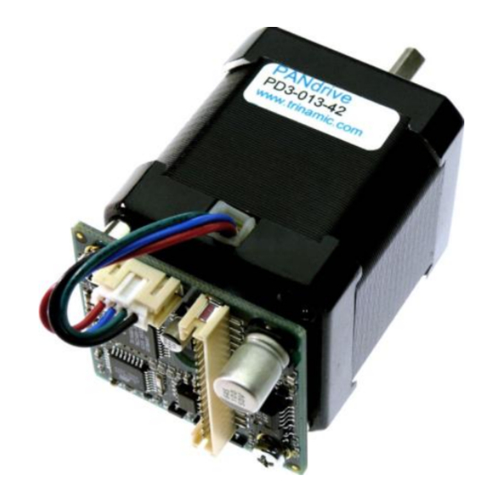
The PD-013-42 is a mechatronic stepper motor module with step-/direction interface plus remote configuration access. It is based on the TMCM-013-42 one axis stepper motor controller and driver for integration directly on a NEMA-17 motor. With up to 1.5A coil current it operates from a single 7 to 30V power supply. -
Page 5: Order Codes
Table 3.1: PANdrive™ and module order codes Option Host interface -485 RS485 Table 3.2: Option for order code Component parts Description TMCM-013-CABLE Cable loom for module and PANdrive™. Table 3.3: Order code for component parts Copyright © 2011, TRINAMIC Motion Control GmbH & Co. KG... -
Page 6: Electrical And Mechanical Interfacing
RS485 - RS485 remote control access -, TTL input OA1, OA2 Connections for motor coil A OB1, OB2 Connections for motor coil B Table 4.1: Pinning of TMCM-013 and TMCM-013-LA Copyright © 2011, TRINAMIC Motion Control GmbH & Co. KG... -
Page 7: Dimensions
The numbering printed on the 16 pin connector is reversed. The red cable is pin 1. Both connectors are crimp connectors series B4B-PH-SM3-TB, PH-connector. Motor: 4 pin connector Control: 16 pin connector Copyright © 2011, TRINAMIC Motion Control GmbH & Co. KG... -
Page 8: Operational Ratings
Input voltage on GPI 0 ... 5 Output voltage on GPO and Alert (open collector) -150 Output current on GPO and Alert (open collector) Environment temperature °C operation Table 5.1: Operational ratings Copyright © 2011, TRINAMIC Motion Control GmbH & Co. KG... -
Page 9: Step, Direction And Disable Inputs
E: Emitter Step Figure 5.1: Step, direction and disable inputs Examples: = 5V undefined OPTON OPTOFF = 0V 1.5V 4.0V STEP = 20V undefined OPTON OPTOFF = 0V 16.5V 19.0V STEP Copyright © 2011, TRINAMIC Motion Control GmbH & Co. KG... -
Page 10: Functional Description
A reset to factory default is possible. Default address byte is A and default baud rate is 9600 baud. This mode can only be used with an appropriate RS485 interface. Commands are sent with a terminal program. Please refer to the start-up, please Copyright © 2011, TRINAMIC Motion Control GmbH & Co. KG... -
Page 11: Rs485 Commands
“Set motor current”. Microstep Sets the maximum microstep resolution (0: Z, z 0… 6 Resolution max; 6: min). Refer to 0 and Table 7.10 Table 7.1: RS485 commands Copyright © 2011, TRINAMIC Motion Control GmbH & Co. KG... -
Page 12: Motor Current (C) Setting With Rs485 Command
Short circuit detected. Please check motor wiring. Table 7.3: Failure readout in SPI mode In the other two modes the failure analysis consists of only one bit: short circuit or overtemperature no failure Copyright © 2011, TRINAMIC Motion Control GmbH & Co. KG... -
Page 13: Stallguard™ (G)
The bit settings are as follows: Value Description ALARM output is inactive ALARM output is active No function ALARM is set to active when driver detects a failure Table 7.6: Alert adjustments Copyright © 2011, TRINAMIC Motion Control GmbH & Co. KG... -
Page 14: Output Setting (O)
The parameter U changes the baud rate of the module for RS485 communication. Parameter U Baud rate 9600 baud 14400 baud 19200 baud 28800 baud 38400 baud 57600 baud 76800 baud 115200 baud Table 7.9: Baud rate Copyright © 2011, TRINAMIC Motion Control GmbH & Co. KG... -
Page 15: Velocity Mode (V And A)
Alert adjustments (set by command N) Output adjustments (set by command O) RS485 parameters (set by command U) Microstep resolution (set by command Z) Example: ENTER stores all parameters in the EEPROM Copyright © 2011, TRINAMIC Motion Control GmbH & Co. KG... -
Page 16: Microstep Resolution (Z)
This is only true for the average, but the motor still sees an alternating current and thus an alternating magnetic field. Now, care has to be taken in order to keep this current to a value Copyright © 2011, TRINAMIC Motion Control GmbH & Co. KG... -
Page 17: Chopper Mode 3 (Phase And Spi)
Phase mode, so possible values for Z (microstep resolution) are 2, 3 or 4. This mode should only be used in very special occasions and mode 3 should be preferred if a combination of high accuracy at slow movements and high speed is needed. Copyright © 2011, TRINAMIC Motion Control GmbH & Co. KG... -
Page 18: Step/Direction
One step impulse represents one microstep. Calculation of rotations per second (refer to 0): Step input frequency rotations rotations Fullsteps Microstep resolution Copyright © 2011, TRINAMIC Motion Control GmbH & Co. KG... -
Page 19: Firmware Update
DIRSETUP DIRHOLD Figure 7.4: Step and Direction Signal 7.5 Firmware update Start the program TMCM013boot.exe for the firmware update (available on www.trinamic.com): Figure 7.5: Firmware update tool Choose your RS485 connection. Select your Module ID (default is A). Load the new firmware file (e.g. TMCM013_V1.08.hex), to download from www.trinamic.com. -
Page 20: Reset To Factory Default
Turn on the module and switch it off again for removing the short circuit. All settings are now at factory default. pin 1 pin 3 (quadratic) Figure 7.6: Reset to factory default Copyright © 2011, TRINAMIC Motion Control GmbH & Co. KG... -
Page 21: Getting Started
Normally, best results will be achieved when operating the given motor in a range of 50 to 100% of nominal motor current (see motor data sheet). Mode 2 and mode 1 are mainly intended for slow, smooth Copyright © 2011, TRINAMIC Motion Control GmbH & Co. KG... -
Page 22: Motor Velocity
12 V 0.7 mH 3.4 mH 24 V 2.6 mH 18 V 350 mA 1.7 mH 12 V 1.0 mH Table 8.1: Maximum supply voltage regarding motor current and inductivity Copyright © 2011, TRINAMIC Motion Control GmbH & Co. KG... -
Page 23: Connecting Motor And Power Supply
Power supply ripple due to the chopper operation should be kept at a maximum of a few 100mV. Therefore we recommend to keep power supply cables as short as possible use large diameter for power supply cables Copyright © 2011, TRINAMIC Motion Control GmbH & Co. KG... -
Page 24: Connections For Step/Direction Mode
USB to RS485 adapter Terminal TMCM-013 Pin 16 Pin 15 Pin 14 optional RS-232-port USB-port Pin 2 Pin 1 PWR 7...28 V Figure 8.5: Contacts for RS485 with an adapter Copyright © 2011, TRINAMIC Motion Control GmbH & Co. KG... -
Page 25: Control With Terminal Program
An acceleration differing from zero is required to get velocities in RS485 mode. Setting or storing this value to the EEPROM disables step/direction control until acceleration is set to zero again (and eventually stored) or the board is reset to factory default. Copyright © 2011, TRINAMIC Motion Control GmbH & Co. KG... -
Page 26: Revision History
1.12 New option stallGuard™ also usable in step/direction mode (controls GPO then) 1.13 Improvement Motor powered (with stand by current) directly after enabling in all modes Table 9.2: Firmware revision Copyright © 2011, TRINAMIC Motion Control GmbH & Co. KG...
Need help?
Do you have a question about the TMCM-013-42 and is the answer not in the manual?
Questions and answers