Table of Contents
Advertisement
Quick Links
Module for Stepper
TMCM-1260 Hardware Manual
Hardware Version V1.10 | Document Revision V1.20 • 2018-05-17
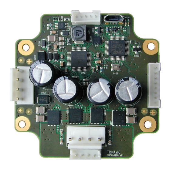
The TMCM-1260 is a single axis motor controller/driver board for 2-phase bipolar stepper motors
with up-to 6A RMS motor current and 48V DC supply. It supports 6-point ramps in addition to linear
ramps.
Applications
• Laboratory Automation
• Manufacturing
• Semiconductor Handling
Simpli ed Block Diagram
EEPROM
USB
RS485
Microcontroller
CAN
I/Os
12... 54V DC
DC/DC
©2018 TRINAMIC Motion Control GmbH & Co. KG, Hamburg, Germany
Terms of delivery and rights to technical change reserved.
Download newest version at:
www.trinamic.com
Read entire documentation.
• Robotics
• Factory Automation
• Test & Measurement
TMCM-1260
MOSFET
Driver
Stage
Motion
Energy Efficient
Controller
Driver
+
TMC262
Pre-Driver
Encoder
Features
• Single axis controller/driver for 2-
phase bipolar stepper motor
• Linear and sixPoint™ ramps
• +24V and +48V DC supply voltage
• Up to 6A RMS motor current
• RS485, CAN & USB interface
• integrated sensOstep encoder and
support for external encoder
• S/D interface
• multi-purpose inputs and outputs
• Life Science
• Biotechnology
• Liquid Handling
Step
Motor
MODULE
Advertisement
Table of Contents

Related Manuals for Trinamic TMCM-1260


Summary of Contents for Trinamic TMCM-1260
- Page 1 Hardware Version V1.10 | Document Revision V1.20 • 2018-05-17 The TMCM-1260 is a single axis motor controller/driver board for 2-phase bipolar stepper motors with up-to 6A RMS motor current and 48V DC supply. It supports 6-point ramps in addition to linear ramps.
-
Page 2: Table Of Contents
TMCM-1260 Hardware Manual • Hardware Version V1.10 | Document Revision V1.20 • 2018-05-17 2 / 30 Contents 1 Features 2 Order Codes 3 Mechanical and Electrical Interfacing 3.1 Size of board .......... -
Page 3: Features
The standard version of the TMCM-1260 offers one analog input (0..10V range), two digital inputs and one open-drain output (100mA load max.) For communication in addition to USB (Micro-USB connector), RS485 and CAN serial interfaces are available. - Page 4 TMCM-1260 Hardware Manual • Hardware Version V1.10 | Document Revision V1.20 • 2018-05-17 4 / 30 • Encoder input for incremental A/B encoder signals (shared with general purpose digital inputs) • 1 analog input (0..10V nom. input range) • HOME switch input (shared with analog input) Mechanical data •...
-
Page 5: Order Codes
On request a version with 3 analog inputs (0..10V) is available instead of one analog and two digital inputs on the I/O connector of the TMCM-1260. As this is an assembly version with different components concerning these inputs, all mechanical data and all other electrical data will be the same. - Page 6 TMCM-1260 Hardware Manual • Hardware Version V1.10 | Document Revision V1.20 • 2018-05-17 6 / 30 The TMCM-1260 is also available as motor mounted version together with a selection of NEMA23 / NEMA24 ange size stepper motor. Please refer to PD57/60-x-1260 PANdrive hardware manual for further details.
-
Page 7: Mechanical And Electrical Interfacing
TMCM-1260 Hardware Manual • Hardware Version V1.10 | Document Revision V1.20 • 2018-05-17 7 / 30 3 Mechanical and Electrical Interfacing 3.1 Size of board The board with the controller/driver electronics has an overall size of 60mm x 60mm x 26mm without mating connectors. -
Page 8: Connectors
8 / 30 4 Connectors The TMCM-1260 offers six connectors altogehter. There is one power supply connector and two interface connectors - one with ve pins for RS485 and CAN and a dedicated micro-USB connector. All other inputs and outputs are concentrated on one 8 pin connector. Furthermore, there is one connection for the stepper motor with four pins with a choice between two connectors with different size, pitch and current... -
Page 9: Power Supply Input Connector
Table 3: Connector Types and Mating Connectors of the TMCM-1260 4.1 Power Supply Input Connector The TMCM-1260 offers one 4pin JST VH series power supply input connector. In addition to main power supply input and related ground connection this connector offers a separate logic supply input with the option to keep the on-board logic alive while the driver stage is switched off. -
Page 10: Motor Connector
Do not mix-up power supply connector and the larger motor connector! 4.3 RS485 + CAN Connector For serial communication the TMCM-1260 offers selection between RS485, CAN and USB interfaces. While the USB interface is available for con guration and service of the board, mainly (e.g. parameter settings, rmware updates) a 5-pin JST PH series connector offers 2-wire RS485 and CAN interfaces for in system... -
Page 11: Usb Connector
Table 7: USB Connector Pin Assignment 4.5 I/O Connector The TMCM-1260 offers several inputs (two of them optically isolated) and one digital (open-drain) output. The inputs include support for stop switches (left and right), home switch, step/direction, incremental A/B channel encoder and analog (0. . . +10V) input. All this functionality is available via one 8pin JST PH series I/O connector. -
Page 12: On-Board Leds
TMCM-1260 Hardware Manual • Hardware Version V1.10 | Document Revision V1.20 • 2018-05-17 12 / 30 Label Direction Description IN1/ENC_A Input General purpose digital input Incremental encoder input channel A +24V tolerant, programmable pull-up (for IN1/IN2 together) to +5V IN2/ENC_B... -
Page 13: Reset To Factory Defaults
13 / 30 6 Reset to Factory Defaults It is possible to reset all settings in rmware for the TMCM-1260 to factory defaults without establishing a working communication connection. This might be helpful in case communication parameters of the preferred interface have been set to unknown values or got lost. -
Page 14: Analog Input In0
7.2 Digital inputs IN1 and IN2 The TMCM-1260 offers two digital inputs IN1 and IN2 which accept signals between 0 and 30V with voltages above approx. 2.9V recognized as logical ’1’ and below 1V as logical ’0’. Both inputs offer intergated pull-ups to +5V which can be switched on or off... -
Page 15: Home/Stop_L/Stop_R Switch Inputs
Figure 6: Digital inputs IN1 and IN2 7.3 HOME/STOP_L/STOP_R switch inputs The TMCM-1260 offers two optically isolated inputs which can be used as left (STOP_L) and right (STOP_R) stop switch inputs. When enabled in software the STOP_L switch input will stop motor movement in negative direction (step counter decreasing) while activated. -
Page 16: Step/Direction Inputs
Step/Dir inputs of the TMCM-1260. Please note that these signals should be 24V signals. For lower voltage signals a simple small signal transistor maybe inserted as level converter. -
Page 17: Communication
17 / 30 8 Communication 8.1 RS485 For remote control and communication with a host system the TMCM-1260 provides a two wire RS485 bus interface. For proper operation the following items should be taken into account when setting up an RS485 network: 1. -
Page 18: Can
Figure 12: RS485 bus lines with Pro bus™recommended line termination 8.2 CAN For remote control and communication with a host system the TMCM-1260 provides a CAN bus interface. Please note that the CAN interface is not available in case USB is connected. For proper operation the following items should be taken into account when setting up a CAN network: 1. - Page 19 Especially for longer busses and/or multiple nodes connected to the bus and/or high communication speeds, the bus should be properly terminated at both ends. The TMCM-1260 does not integrate any termination resistor. Therefore, 120 Ohm termination resistors at both ends of the bus have to be added externally.
-
Page 20: Motor Driver Current
TMCM-1260 Hardware Manual • Hardware Version V1.10 | Document Revision V1.20 • 2018-05-17 20 / 30 9 Motor driver current The on-board stepper motor driver operates current controlled. The driver current may be programmed in software with 32 effective scaling steps in hardware. - Page 21 TMCM-1260 Hardware Manual • Hardware Version V1.10 | Document Revision V1.20 • 2018-05-17 21 / 30 Motor current setting Current scaling step Motor current I Motor current I COIL COIL in software (TMCL) (CS) peak 160. . . 167 5.332 3.770...
-
Page 22: Functional Description
10 Functional Description The TMCM-1260 is a highly integrated single axis controller/driver module for stepper motors with up-to 6A RMS / 8.4A peak motor coil current. The TMCM-1260 can be controlled via RS485, CAN or USB serial interfaces. The TMCM-1260 comes with the PC based software development environment TMCL-IDE for the Trinamic Motion Control Language (TMCL™). -
Page 23: Operational Ratings And Characteristics
TMCM-1260 Hardware Manual • Hardware Version V1.10 | Document Revision V1.20 • 2018-05-17 23 / 30 11 Operational Ratings and Characteristics NOTICE Never Exceed the absolute maximum ratings! Keep the power supply voltage below the upper limit of +54V! Otherwise the board electronics will seriously be damaged! Especially, when the selected operating voltage is near the upper limit a regulated power supply is highly recommended. - Page 24 TMCM-1260 Hardware Manual • Hardware Version V1.10 | Document Revision V1.20 • 2018-05-17 24 / 30 Operational Ratings of the I/Os Symbol Parameter Unit Table 12: Operational ratings of I/Os Operational Ratings of the RS485 Interface Symbol Parameter Unit Number of nodes connected to single RS485 network RS485 Max.
-
Page 25: Abbreviations Used In This Manual
TMCM-1260 Hardware Manual • Hardware Version V1.10 | Document Revision V1.20 • 2018-05-17 25 / 30 12 Abbreviations used in this Manual Abbreviation Description Integrated Development Environment Light Emmitting Diode Root Mean Square value TMCL TRINAMIC Motion Control Language Table 15: Abbreviations used in this Manual ©2018 TRINAMIC Motion Control GmbH &... -
Page 26: Figures Index
TMCM-1260 Hardware Manual • Hardware Version V1.10 | Document Revision V1.20 • 2018-05-17 26 / 30 13 Figures Index Board dimensions, position of mount- Step/Direction input ..ing holes and position (pin 1) of con-... -
Page 27: Tables Index
TMCM-1260 Hardware Manual • Hardware Version V1.10 | Document Revision V1.20 • 2018-05-17 27 / 30 14 Tables Index TMCM-1260 Order Code ..General operational ratings of the TMCM-1260 Cable Loom .. -
Page 28: Supplemental Directives
15.5 Disclaimer: Life Support Systems TRINAMIC Motion Control GmbH & Co. KG does not authorize or warrant any of its products for use in life support systems, without the speci c written consent of TRINAMIC Motion Control GmbH & Co. KG. -
Page 29: Collateral Documents & Tools
In particular, this also applies to the stated possible applications or areas of applications of the product. TRINAMIC products are not designed for and must not be used in connection with any applications where the failure of such products would reasonably be expected to result in signi cant personal injury or death (safety-Critical Applications) without TRINAMIC’s speci c written consent. -
Page 30: Revision History
TMCM-1260 Hardware Manual • Hardware Version V1.10 | Document Revision V1.20 • 2018-05-17 30 / 30 16 Revision History 16.1 Hardware Revision Version Date Author Description V1.0 2017-OCT-30 Initial version V1.1 2018-FEB-21 Linear pre-regulator for driver supply added for better heat distribu-...
Need help?
Do you have a question about the TMCM-1260 and is the answer not in the manual?
Questions and answers