Table of Contents

Subscribe to Our Youtube Channel
Related Manuals for Trinamic TMCM-342


Summary of Contents for Trinamic TMCM-342
- Page 1 TMCM-342 3 - Axis Stepper Motor Motion Control Module with Step / Direction outputs Manual Version: 1.01 December 9 , 2008 Trinamic Motion Control GmbH & Co. KG Sternstraße 67 D – 20357 Hamburg, Germany http://www.trinamic.com...
-
Page 2: Table Of Contents
Step-/Direction output ............................. 12 Connecting the drivers ............................ 12 5.5.1 Connecting the TMCM-342 to a power driver module with Step/Direction-Interface ..12 5.5.2 Connecting the TMCM-342 to drivers with an SPI-Interface ............15 Power supply requirements with drivers ....................16 Ramp Profiles .............................. - Page 3 Figure 5.10: Application Environment using the SPI-Interface ................15 Figure 5.11: Application with an SPI-stepper motor driver ................... 16 Figure 5.12: Power supply requirements for TMCM-342 with additional driver ..........16 Figure 5.13: Power supply requirements for TMC-Modules in a bus system ............ 17 Figure 5.14: Velocity profile in ramp mode ........................
-
Page 4: Features
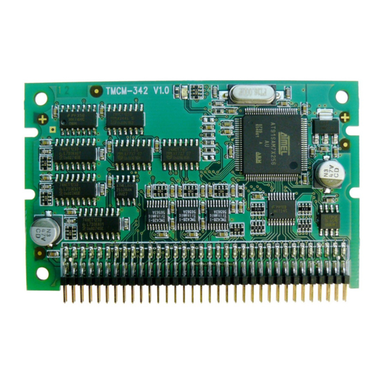
4/26 1 Features The TMCM-342 is a triple axis stepper motor controller module for external power drivers with step / direction interface. With its very small size it is dedicated to embedded applications, where centralized or de-centralized high power drivers are desired. The board can be connected to a baseboard or customized electronics with a pin connector. -
Page 5: Life Support Policy
Specifications are subject to change without notice. Copyright © 2008, TRINAMIC Motion Control GmbH & Co. KG... -
Page 6: Electrical And Mechanical Interfacing
2 (PCB) Note: all dimensions in mm Figure 3.1: Dimensions The size of the module (80x50mm) is the same as of many other Trinamic motion control modules. It also uses the same connector. The 68 pin connector has a 2.0mm pitch. -
Page 7: Connecting The Module
RS-485 Direction STEP_M0 InOut CAN - SPI_M1_CLK RS-232 RxD DIR_M0 InOut CAN + SPI_M2_OUT RS-232 TxD Table 3.1: Pinout of the 68-Pin Connector Figure 3.2: Pin order of the connector Copyright © 2008, TRINAMIC Motion Control GmbH & Co. KG... -
Page 8: Operational Ratings
Table 4.1: Operational Ratings 5 Functional Description In Figure 5.1 the main parts oft the TMCM-342 module are shown. The module mainly consists of three TMC428 motion controllers, the TMCL program memory (EEPROM) and the host interfaces (RS- 232, RS-485 and CAN). -
Page 9: System Architecture
SPI-Interface can be added, but this module is mainly intended for use with Step/Direction drivers. Power Supply The power supply for the TMCM-342 is +5VDC for module functionality. Please use all listed pins for the power supply inputs and ground parallel. Refer to 6. Function... -
Page 10: Host Communication
Table 5.3: Pinout for RS-232 Connection Note: The module only provides serial signals with TTL level. For using RS232, a suitable RS232 level shifter (like MAX202) has to be added by the user. Copyright © 2008, TRINAMIC Motion Control GmbH & Co. KG... -
Page 11: Figure 5.3: Connecting Rs-232
2, 4, 6, 8, 10 Connect to ground Table 5.4: Pinout for RS-485 Connection Note: The TMCM-342 module only provides TTL level signals. For using RS485 a suitable RS485 tansceiver (like MAX485) has to be added by the user. 68-Pin-Connector... -
Page 12: Step-/Direction Output
Figure 5.5: Step-/Direction output signals Connecting the drivers Because there are no stepper motor drivers included on the TMCM-342, an Add-On-Board has to be developed to drive the stepper motors. Some examples of Trinamic´s own driver modules are added below. Please refer to www.trinamic.com... -
Page 13: Figure 5.6: Application Environment Using The Step/Direction-Interface
Motor 0 Motor 1 Motor 2 Figure 5.6: Application Environment using the Step/Direction-Interface Examples: Connection of the TMCM-342 with the Monopack2 (power driver module with a Step/Direction-Interface), TMCM-023 or TMCM-013. TMCM-342 Power module with Pin 68 Step/Direction Interface, e.g. -
Page 14: Figure 5.8: Application With Tmcm-023 With 3 Step/Direction-Interfaces (5V Inputs Required, Please See Latest Tmcm-023 Documentation For Modifications)
Pin 36 STEP_M1 Pin 34 DIR_M0 Pin 32 STEP_M0 Pin 6 Pin 4 Pin 2 +5V DC VS = 7...28V Motor connection Figure 5.9: Application with TMCM-013 with a Step/Direction-Interface Copyright © 2008, TRINAMIC Motion Control GmbH & Co. KG... -
Page 15: Connecting The Tmcm-342 To Drivers With An Spi-Interface
5.5.2 Connecting the TMCM-342 to drivers with an SPI-Interface The pins connecting the TMCM-342 with the Add-On-Board using the SPI-Interface are listed in Table 5.6. This is only listed here for the sake of completeness. It is not directly supported by the firmware of the TMCM-342. -
Page 16: Power Supply Requirements With Drivers
Figure 5.11: Application with an SPI-stepper motor driver Power supply requirements with drivers The TMCM-342 is supplied with +5VDC, the drivers need an additional power supply for the motor supply. Please connect all listed pins for the power supply inputs and ground in parallel. It is recommended to use capacitors of some 1000µF and a choke close to the drivers. -
Page 17: Figure 5.13: Power Supply Requirements For Tmc-Modules In A Bus System
Please make sure that the GND lines of the CAN sender and the module(s) and power supplies are connected by a cable. Copyright © 2008, TRINAMIC Motion Control GmbH & Co. KG... -
Page 18: Ramp Profiles
18/26 Ramp Profiles The speed profile is automatically worked out by the TMCM-342 from the values for the minimum speed, maximum speed and acceleration specified by the user with the TMCL. Two modes of operation for the course of velocity are available for selection. -
Page 19: Reference Switches
Table 5.7: Pinout of the reference switch inputs 5.8.1 Left and right limit switches The TMCM-342 can be configured so that a motor has a left and a right limit switch (Figure 5.16). The motor stops when the traveler has reached one of the limit switches. -
Page 20: One Limit Switch For Circular Systems
Chip Select Bit0 SPI_SEL1 Chip Select Bit1 SPI_SEL2 Chip Select Bit2 SPI_CLK SPI Clock SPI_MISO SPI Serial Data In SPI_MOSI SPI Serial Data Out Table 5.8: Pinout Serial Peripheral Interface Copyright © 2008, TRINAMIC Motion Control GmbH & Co. KG... -
Page 21: Additional Inputs And Outputs
Emergency stop Table 5.10: Miscellaneous Connections The functionality of the shutdown pin is configurable using in TMCL with global parameter 80 (please see the TMCL reference manual for information on this). Copyright © 2008, TRINAMIC Motion Control GmbH & Co. KG... -
Page 22: Putting The Tmcm-342 Into Operation
22/26 6 Putting the TMCM-342 into Operation On the basis of a small example it is shown step by step how the TMCM-342 is set into operation. Experienced users could skip this chapter and proceed to chapter 6. Example: The following application is to implement with the TMCL-IDE Software development environment in the TMCM-342 module. -
Page 23: Migrating From The Tmcm-302 To The Tmcm-342
TMCM-302 without problems. The connector of the TMCM-342 is identical to the connector of the TMCM-302, so that a TMCM-342 can just be plugged into a slot that has originally been designed for a TMCM-302 (it can also use the same base boards as the TMCM-302). Also the TMCL firmware of the TMCM-342 module is highly compatible with the TMCM-302. -
Page 24: Tmcm-342 Operational Description
The change in the pulse rate per time unit (pulse frequency change per second – the acceleration a is given by pulse ramp This results in an acceleration in fullsteps of: where “af” means acceleration in fullsteps usrs Copyright © 2008, TRINAMIC Motion Control GmbH & Co. KG... -
Page 25: Tmcl
10 CANopen The TMCM-342 module can also be used with the CANopen protocol. For this purpose, a special CANopen firmware has to be installed. To do this, download the latest version of the TMCM-342 CANopen firmware from the Trinamic website or use the version provided on the TechLib CD and install it using the firmware update function of the TMCL-IDE (Setup/Install OS). -
Page 26: Revision History
Version Comment Description 4.07 Initial release Please refer to TMCL documentation 4.15 Actual release Table 11.3: Firmware Revisions 12 References [TMCL] TMCL manual (see http://www.trinamic.com) [CANopen] CANopen manual (see http://www.trinamic.com) Copyright © 2008, TRINAMIC Motion Control GmbH & Co. KG...
Need help?
Do you have a question about the TMCM-342 and is the answer not in the manual?
Questions and answers