Table of Contents
Advertisement
Quick Links
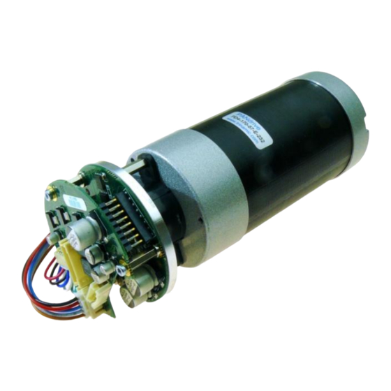
MECHATRONIC DRIVES WITH BLDC MOTOR
V 1.10
HARDWARE MANUAL
+
+
+
+
TRINAMIC Motion Control GmbH & Co. KG
Hamburg, Germany
www.trinamic.com
170
TMCM-
+
controller / driver module
up to 10A RMS / 12... 48V DC
CAN, RS232/RS485 (optional)
+
170
PDx-
+
mechatronic
57 mm BLDC servo motor
up to 10A RMS / 12... 48V DC
CAN, RS232/RS485 (0ptional)
incremental encoder
hall sensors
+
PANdrives
57
-
57
-
-E
device
with
Advertisement
Table of Contents

Subscribe to Our Youtube Channel
Summary of Contents for Trinamic TMCM-170-57
- Page 1 10A RMS / 12… 48V DC CAN, RS232/RS485 (optional) PDx- mechatronic device with 57 mm BLDC servo motor up to 10A RMS / 12… 48V DC CAN, RS232/RS485 (0ptional) incremental encoder hall sensors TRINAMIC Motion Control GmbH & Co. KG Hamburg, Germany www.trinamic.com...
-
Page 2: Table Of Contents
Temperature, current and voltage monitoring functions ..............15 Programmable motor current limit ......................16 Revision history ................................17 Document revision ............................17 Firmware revision ............................. 17 References ..................................17 Appendix ..................................18 Copyright © 2011, TRINAMIC Motion Control GmbH & Co. KG... -
Page 3: Life Support Policy
Specifications are subject to change without notice. Copyright © 2011, TRINAMIC Motion Control GmbH & Co. KG... -
Page 4: Features
CAN interface and RS232 or RS485 integrated Integrated Protection: reverse polarity and overload / overtemperature / overvoltage TRINAMIC TMCL™ protocol and TMCL™ software environment for parameterizing and for update and for programming of standalone mode 1024 entry 10 bit motor sine commutation table ... -
Page 5: Order Codes
RS232 and CAN interface -485 RS485 and CAN interface Table 3.2: Options for order codes Component parts Description TMCM-170-CABLE Cable loom for module and PANdrive™. Table 3.3: Order codes for component parts Copyright © 2011, TRINAMIC Motion Control GmbH & Co. KG... -
Page 6: Electrical And Mechanical Description
H1, H2, H3 Hall sensor signals (5V TTL input with integrated pull-up resistor to 5V) Positive power supply voltage (reverse polarity protected) Other pins Leave all other pins unconnected! Table 4.1: Pinning Copyright © 2011, TRINAMIC Motion Control GmbH & Co. KG... -
Page 7: Application Circuit
TMCM-170 Motor Encoder 48V system Mech. Axis power supply Encoder optional overvoltage Place unit near suppressor: encoder / motor high power zener / zener transistor circuit Figure 4.2: Application circuit Copyright © 2011, TRINAMIC Motion Control GmbH & Co. KG... -
Page 8: Dimensions
Top view of Driver board 30,50 32,00 46,77 All values are in millimeters 61,00 I/O-Board PD-170 Driver-Board Gap pad Metal plate Encoder BLDC Motor Figure 4.3: Dimensions of TMCM-170 and PD-170 Copyright © 2011, TRINAMIC Motion Control GmbH & Co. KG... -
Page 9: Connectors
0.35 Line to Line Inductance Max Peak Current 16.5 20.5 Lenth (L Rotor Inertia kgm² x 10 17,3 Mass 1,25 Related TRINAMIC PANdrive™ PD4-170-57 PD5-170-57 Table 4.2: Motor technical data Copyright © 2011, TRINAMIC Motion Control GmbH & Co. KG... - Page 10 TMCL-IDE. Adjustments for QBL5704-94-04-032 Switch the reverse hall sensor polarity off and the reverse encoder direction on. Use the basic control and diagnostics software or TMCL-IDE. Copyright © 2011, TRINAMIC Motion Control GmbH & Co. KG...
-
Page 11: Operational Ratings
Encoder count rate (signals 50% duty cycle) 13.3 Environment temperature operating °C Temperature of the bottom (driver) PCB, as measured by <105 °C board the integrated sensor. Table 5.1: Operational ratings Copyright © 2011, TRINAMIC Motion Control GmbH & Co. KG... -
Page 12: Power Supply Requirements
“inactive” level to the line, when no driver is on. Typically, use a 1K resistor to + 5V for RS485+ line and a 1K resistor to GND for the RS485- line at some point of the network. Copyright © 2011, TRINAMIC Motion Control GmbH & Co. KG... -
Page 13: Functional Description
To first find the N-channel reference position, the motor is turned by up to one rotation, until the N-channel is found positive. The velocity and direction can be specified using the parameter “Sine Init Velocity”. After finding the reference position, the Copyright © 2011, TRINAMIC Motion Control GmbH & Co. KG... -
Page 14: Encoder Setting
Set Encoder Null Set Encoder Null Polarity to Polarity to binary 011 binary 001 Enc-A Enc-B Enc-N (index) CW turn CCW turn CW turn CCW turn zero event zero event Copyright © 2011, TRINAMIC Motion Control GmbH & Co. KG... -
Page 15: Hall Sensor Only Operation W/O Encoder
The power stage on the module has exceeded a critical temperature warning of 115°C. The motor becomes switched off, until temperature falls below 105°C. The measurement is correct to about +/-10°C Table 6.1: LED outputs Copyright © 2011, TRINAMIC Motion Control GmbH & Co. KG... -
Page 16: Programmable Motor Current Limit
Clear Target Distance in order to stop the ramp generator, when the deviation between the positions becomes too large. The effect of this may look somehow weird if the user does not expect it. Copyright © 2011, TRINAMIC Motion Control GmbH & Co. KG... -
Page 17: Revision History
Table 7.2: Firmware revision 8 References [TMCL] TMCL™ Manual, www.trinamic.com [TMCM –170] Reference and Programming Manual, www.trinamic.com QBL5704 Manual QBL5704 BLDC servo motor manual, www.trinamic.com HEDS-5640#A12 info HEDS-5640#A12 encoder information http://www.avagotech.com Copyright © 2011, TRINAMIC Motion Control GmbH & Co. KG... -
Page 18: Appendix
STAP 6, 0 //Store Max Current STAP 4, 0 //Store Max Pos. Velocity STAP 165, 0 //Store Commutation Offset ! SGP 249, 0, 3 //Init Mode 3 ( N-Kanal ) STOP Copyright © 2011, TRINAMIC Motion Control GmbH & Co. KG...


Need help?
Do you have a question about the TMCM-170-57 and is the answer not in the manual?
Questions and answers