Trinamic TMCM-351 Hardware Manual
3-axis stepper motor controller and driver board 2.8a rms 7...28.5v dc spi, rs232, rs485, can, and usb encoder interface
Hide thumbs
Also See for TMCM-351:
- Manual (89 pages) ,
- Firmware manual (80 pages) ,
- Hardware manual (15 pages)
Table of Contents
Advertisement
Quick Links
Advertisement
Table of Contents

Subscribe to Our Youtube Channel
Related Manuals for Trinamic TMCM-351


Summary of Contents for Trinamic TMCM-351
- Page 1 MODULES FOR STEPPER MOTORS MODULES V 1.06 HARDWARE MANUAL TMCM- 3-axis stepper motor controller and driver board 2.8A RMS 7… 28.5V DC SPI, RS232, RS485, CAN, and USB Encoder interface TRINAMIC Motion Control GmbH & Co. KG Hamburg, Germany www.trinamic.com...
-
Page 2: Table Of Contents
Calculation: Velocity and acceleration vs. microstep and fullstep frequency ........25 TMCL™ ................................... 27 CANopen ..................................28 10 Revision history ................................29 10.1 Document revision ............................29 10.2 Hardware revision ............................. 29 11 References..................................30 Copyright © 2011, TRINAMIC Motion Control GmbH & Co. KG... -
Page 3: Life Support Policy
Specifications are subject to change without notice. Copyright © 2011, TRINAMIC Motion Control GmbH & Co. KG... -
Page 4: Features
TMCM-351 Hardware Manual (V1.06 / 2011-NOV-14) 2 Features The TMCM-351 is a powerful three axes bipolar stepper motor controller/driver board with encoder interface for all three axes and a large number of general purpose digital and analog input/outputs. Several different serial communication interfaces are available. -
Page 5: Order Codes
TMCM-351 Hardware Manual (V1.06 / 2011-NOV-14) 3 Order codes The TMCM-351 is available with encoder interface and with standard TMCL™ firmware or CANopen firmware. Dimensions Order code Description TMCM-351-E TMCM-351 with encoder interface and TMCL™ 160 x 100 x 29 mm... -
Page 6: Mechanical And Electrical Interfacing
4 Mechanical and electrical interfacing 4.1 Dimensions The TMCM-351 three axes controller driver board has a board size of 160mm x 100mm (standard euro board format). There are four mounting holes altogether for M3 screws placed at a distance of 4mm from each corner of the board (Figure 4.1). -
Page 7: Connectors
TMCM-351 Hardware Manual (V1.06 / 2011-NOV-14) 4.2 Connectors The TMCM-351 has connectors for three motors, related reference switches, three encoders, analog and digital inputs and outputs and several serial interfaces (RS232, RS485, CAN and USB). On the next page you will find a table with all connector types and their mating ones. - Page 8 8289, 10 pol., DIN 41651, 2.54 DIN41651, 2.54 (AVX 00 8380 010 000 01 0) (AVX 00 8290 010 001 01 1) Table 4.1: Connectors and mating connectors of the TMCM-351 Copyright © 2011, TRINAMIC Motion Control GmbH & Co. KG...
-
Page 9: Power Connector
Table 4.3: Motor connector (detachable screw connector) Label Description Motor 0/1/2, coil B Motor_0/1/2_B- Motor_0/1/2_B+ Motor 0/1/2, coil B Motor_0/1/2_A- Motor 0/1/2, coil A Motor_0/1/2_A+ Motor 0/1/2, coil A Table 4.4: Motor connector (crimp connector) Copyright © 2011, TRINAMIC Motion Control GmbH & Co. KG... -
Page 10: Reference Connector
+5V supply output for active switches Table 4.6: Reference connector (crimp connector) To motion controller TMC428 To motion controller TMC428 Figure 4.3: Internal Reference connector circuit (for one motor axis) Copyright © 2011, TRINAMIC Motion Control GmbH & Co. KG... - Page 11 TMCM-351 Hardware Manual (V1.06 / 2011-NOV-14) 4.2.3.1 Left and right limit switches The TMCM-351 can be configured so that a motor has a left and a right limit switch (Figure 4.4). The motor stops when the traveler has reached one of the limit switches.
-
Page 12: Analog Input Connector
Pins not used / not connected Table 4.9: RS232 connector Attention: Please verify the setting of J2 (selection of RS232 or RS485 interface in section 4.3.2) for a proper operation of the RS232 connection. Copyright © 2011, TRINAMIC Motion Control GmbH & Co. KG... -
Page 13: Can Connector
For extension of the available inputs and outputs an SPI interface is available. A standard 2.54mm pitch two row header is used as connector for the external SPI interface. Please connect as shown below: Label Label SPI_MOSI SPI_MISO SPI_CLK SPI_SEL0 SPI_SEL2 SPI_SEL1 +5V_output Table 4.12: SPI connector Copyright © 2011, TRINAMIC Motion Control GmbH & Co. KG... -
Page 14: I/O Connector
(please refer to section 4.3.5 for detailed information). +24V +24V +24V +24V galvanic isolation freewheeling diode integrated on-board opto-coupler Figure 4.7: Examples for possible wirings for GPI and GPO Copyright © 2011, TRINAMIC Motion Control GmbH & Co. KG... - Page 15 IN_0 IN_1 IN_2 IN_3 IN_4 IN_5 +24V IN_6 IN_7 GND GND GND GND GND GND GND GND /SHUTDOWN >=1 >=1 >=1 /ENABLE /DRIVER ENABLE Figure 4.8: Internal I/O connector circuit Copyright © 2011, TRINAMIC Motion Control GmbH & Co. KG...
-
Page 16: Encoder_0/1/2 Connector
Label Label Encoder_0/1/2_N+ Encoder_0/1/2_N- Encoder_0/1/2_A+ Encoder_0/1/2_A- +5V_output +5V_output Encoder_0/1/2_B+ Encoder_0/1/2_B- Table 4.13: Encoder connector Encoder A Encoder B Encoder N Figure 4.9: Internal encoder connector circuit (for one encoder connector) Copyright © 2011, TRINAMIC Motion Control GmbH & Co. KG... -
Page 17: Jumpers
This 3-pin single row header is used for selecting one of two desired serial interfaces: RS232 or RS485 using a jumper: RS 232 interface RS 485 interface selection selection Figure 4.11: RS232/RS485 interface selection Copyright © 2011, TRINAMIC Motion Control GmbH & Co. KG... -
Page 18: J3: Can Bus Termination
The /Shutdown input pin has to be connected to the supply voltage in order to enable the driver stages for all three stepper motor axes. A jumper between pin 19 and pin 20 can be used to permanently enable drivers. Figure 4.13: Enable all driver stages permanently Copyright © 2011, TRINAMIC Motion Control GmbH & Co. KG... -
Page 19: Operational Ratings
TMCM-351 TMCL™ firmware manual [TMCL]). Same value for CANopen firmware (see CANopen manual [CANopen]) **) Please note: tested with setting SAP 6, <motor>, 180 (see TMCM-351 TMCL™ firmware manual [TMCL]). Same value for CANopen firmware (see CANopen manual [CANopen]) Symbol... - Page 20 *) Number of nodes per CAN or RS485 network highly depends on communication speed and cable length. Higher speeds and longer cables will reduce max. feasible number of nodes in one network. Copyright © 2011, TRINAMIC Motion Control GmbH & Co. KG...
-
Page 21: Functional Description
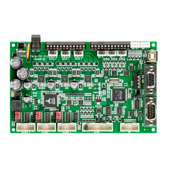
TMCM-351 Hardware Manual (V1.06 / 2011-NOV-14) 6 Functional description In figure 6.1 the main parts of the TMCM-351 are shown. The module mainly consists of the µC (connected to the EEPROM TMCL™ memory), the TMC428 motion controller (which controls up to three axes), three TMC249 stepper drivers, three external MOSFETs, the interfaces (RS232, RS485, USB, and CAN), I/Os, and the encoder interface based on the TMC423. -
Page 22: Eeprom
The TMCM-351 module is equipped with a circuit that extends the microstep resolution of the TMC249 chips to true 64 times microstepping. The maximum peak coil current of each stepper motor driver chip is 1500mA. -
Page 23: Stallguard™ Adjusting Tool
Abort button. The result can also be exported to Excel or to a text file by using the Export button. Figure 6.3: The stallGuard™ profiler Copyright © 2011, TRINAMIC Motion Control GmbH & Co. KG... -
Page 24: Microstep Resolution
6.3 Microstep resolution The TMCM-351 supports a true 64 microstep resolution. To meet your needs, the microstep resolution can be set using the TMCL™ software. The default setting is 64 microsteps, which is the highest resolution. For setting the microstep resolution with the TMCL™ firmware use instruction 5: SAP, type 140: microstep resolution. -
Page 25: Tmcm-351 Operational Description
The change in the pulse rate per time unit (pulse frequency change per second – the acceleration a) is given by pulse ramp This results in acceleration in fullsteps of: af with af: acceleration in fullsteps usrs Copyright © 2011, TRINAMIC Motion Control GmbH & Co. KG... - Page 26 Calculation of the number of rotations: A stepper motor has e.g. 72 fullsteps per rotation. 1907 fullsteps rotation 1907 1589 fullsteps rotation Copyright © 2011, TRINAMIC Motion Control GmbH & Co. KG...
-
Page 27: Tmcl
TMCL™, the TRINAMIC Motion Control Language, is described in separate documentations, which refer to the specific products (e.g. TMCM-351 TMCL™ Firmware Manual [TMCL]). The manuals are provided on the TMC TechLibCD and on www.trinamic.com. Please refer to these sources for updated data sheets and application notes. -
Page 28: Canopen
To do that, download the latest version of the TMCM-351 CANopen firmware from the Trinamic website or use the version provided on the TechLib CD and install it using the firmware update function of the TMCL-IDE (Setup/Install OS). The TMCM-351 module is then ready to be used with CANopen. -
Page 29: Revision History
REF switch and encoder input circuits added Table 10.1: Document revision 10.2 Hardware revision Version Date Description 1.00 2008-AUG-25 First prototypes 1.10 2008-DEC-22 Series version 1.20 2009-DEC-14 New encoder interface IC Table 10.2: Hardware revision Copyright © 2011, TRINAMIC Motion Control GmbH & Co. KG... -
Page 30: References
TMCM-351 TMCL™ Firmware Manual (see www.trinamic.com) [CANopen] TMCM-351 / TMCM-43x CANopen Manual (see www.trinamic.com) [TMCL-IDE] TMCL-IDE User Manual (see www.trinamic.com) [QSH5718] QSH5718 Manual (see www.trinamic.com) [QSH6018] QSH6018 Manual (see www.trinamic.com) Copyright © 2011, TRINAMIC Motion Control GmbH & Co. KG...
Need help?
Do you have a question about the TMCM-351 and is the answer not in the manual?
Questions and answers